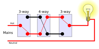
Pick the diagram that is most like the scenario you are in and see if you can wire your switch. Several example circuits using two switches to control a light.
Wiring A 4 Way Switch
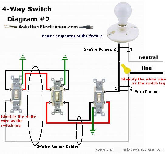
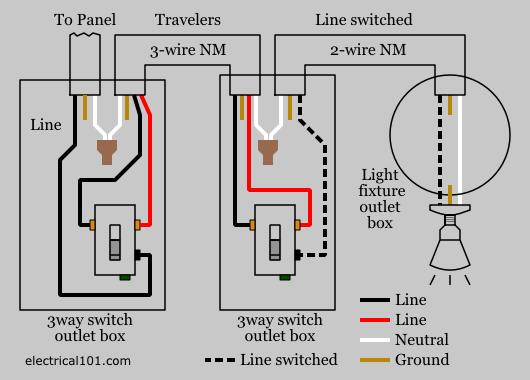
3 way 4 way switch diagram. Wires consisting of a line a load a neutral a pair of travelers and two 3 way switches. The diagrams below show the conventional wiring for 3 way switches in a 4 way configuration. All three way switch and 2 way switch wiring diagrams have the same basic components. Below is a conventional wiring diagram for a 4 way switch configuration. A 4 way switch has five terminals. This 4 way switch diagram 2 shows the power source starting at the fixture.
A 4 way switch must be wired between two 3 way switches as shown in the diagrams on this page. With these diagrams below it will take the guess work out of wiring. A 4 way switch has five terminals. One ground and 4 circuit terminals divided into two matching pairs called travelers. The 4 way switch is on the basement level and there is a 3 way switch in the entry and at the top of the steps on the main floor. If you are trying to troubleshoot a 3 way switch operation then you will need to identify the function of each wire.
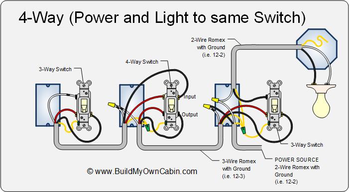
This 4 way switch diagram 1 shows the power source starting at the left 3 way switch. Each pair of traveler terminals should be wired to the traveler wires from one of the 3 way switches in the circuit. This might seem intimidating but it does not have to be. I would have to double check but im 90 certain the power is supplied at the entry level switch or it could be powered at the light. One ground and 4 circuit terminals divided into two matching pairs called travelers. Interested in a 4 way switch wiring diagram.
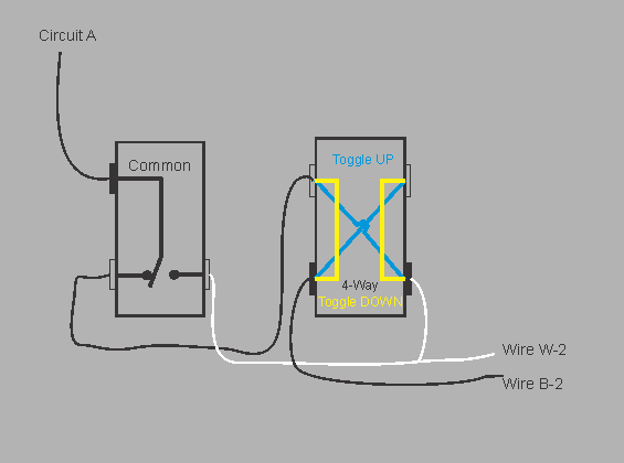
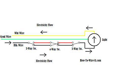
Below is another method for wiring 4 way switches. Take a closer look at a 3 way switch wiring diagram. The electrical switch box that contains the line and load wires may need to be bigger than the other switch boxes especially if there are other wires going into the. This one minute animated tutorial is my clearest presentation of 3 and 4 way switches in action. Unfortunately not all 3 way switches are wired the conventional way. Smarthome sells many types of smart switches and plugs.
A 4 way switch must be wired between two 3 way switches as shown in the diagrams on this page. The white wire of the cable going to the switch is attached to the black line in the fixture box using a wirenut. 4 way switches an animation. 3 way switch diagram tips continuous hot and light feed wire goes on black screw traveler wires go on the brass screws 143 with ground or 123 with ground wire best to use between switches watch all videos below for easy steps. Some have the light between the switches while some have the light at the end. See alternate 3 way switch wiring configuration for another way 3 way switches may be wired.
More 4 way switch wiring diagrams four way switch wiring schematic.
Gallery of 3 Way 4 Way Switch Diagram