If your kw is 24volt start 12volt run. Wiring schematic for series parallel switch sign in to follow this.
Turn Signal Switch Wiring Ford Truck Enthusiasts Forums
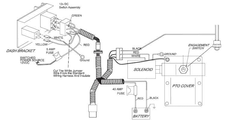
Truck series parallel switch wiring diagram. Parallel wiring gives the signal of the pickup the shortest possible distance to the output jackseries wiring gives the signal a much greater distance to travel. Does anyone know what these switches are called now days. Your set up of 3 maybe to give more cold cranking amps. 2 support topic get support tutorial information. When the starting key is activated the series parallel solenoid coil is energised and the plunger moves disconnecting contact 1 from 3 and contact 2 from 4. Antique classic mack truck articles.
Wiring diagrams r v p truck models when reference is made in this manual to a brand name number or specific tool an equivalent product may. Updated february 23 2017. For example the switch controlling the headlights is at the power end of the circuit. The following diagrams are shown as wiring diagrams rather than schematics for the benefit of the novice. Series circuits parallel circuits or seriesparallel circuits. Im looking for a switch to take two 12 volt batteries and in one position give 12 volt output in parallel.
A series parallel switch consists of four sets of contacts that well call 1 2 3 and 4. There are 3 quick checks that you can perform to break the problem into thirds either a battery problem a parallel switch problem or a starter or high resistance path problem. This wiring uses a 5 way switch includes both humbuckers individually and adds tones using coils from both pickups to create other humbucker style tones. Contacts s2 c and s2 b connect a2 to b1 which places both batteries in series. Either the engine will not turn over most common problem or the engine turns over slower than normal. There should be a series parallel switch close by the battery box which looks similar to these in attached pdf.
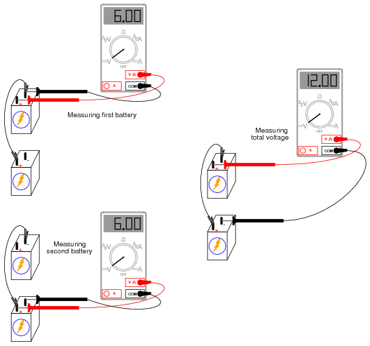
Now when the starter solenoid engages 24 volts is applied to the starter motor. I posted earlier uses 4 6volt batteries two sets of two wired in series effectively giving 2 12 volt batteries. Parallel switch starter problems come in 2 flavors. When the parallel switch is energized contacts s1 c and s1 b connect b2 to terminal b of the starter solenoid. Find their other tutorials. Wiring diagrams 5 wiring diagrams 6 path.
Series parallel switch diagram provided by bmt member dover. The signal having to travel a greater distance experiences more resistance thus getting bigger and beefier as a result. Contacts 1 and 3 and contacts 2 and 4 are connected together as they are spring loaded. And in another position give 24 volt power in series. Submitted october 14 2011.
Gallery of Truck Series Parallel Switch Wiring Diagram