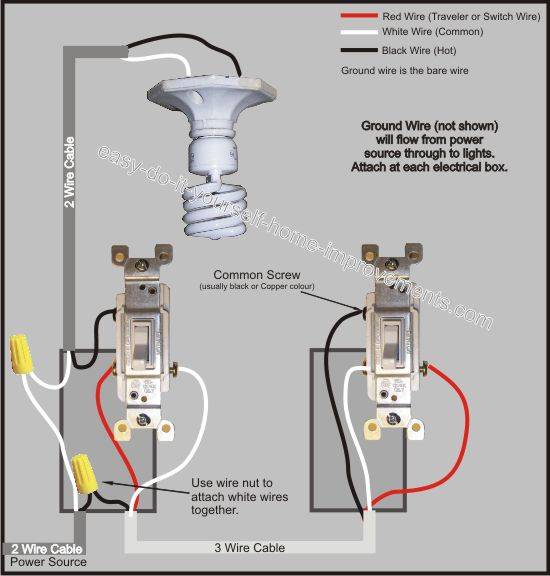
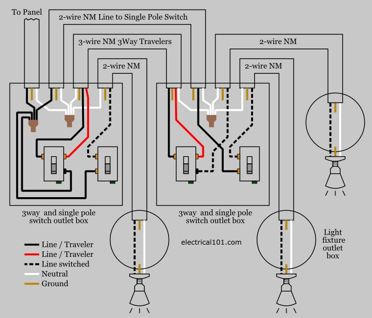
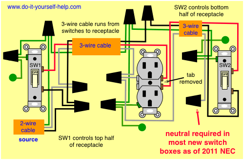
The diagrams below show the conventional wiring for 3 way switches. In this diagram two 3 way switches control a wall receptacle outlet that may be used to control a lamp from two entrances to a room.

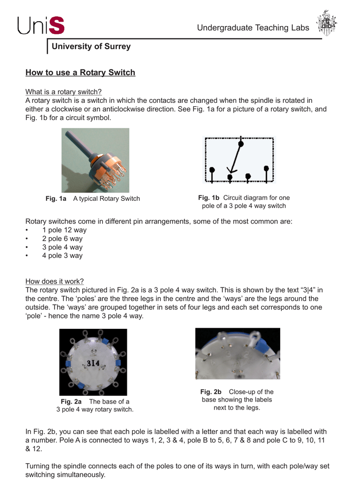
Wiring Diagram 3 Pole 4 Way Rotary Switch Wiring Diagram
2 pole 3 way switch diagram. The wiring is more complicated than a traditional single pole switch but well explain how to make the connections. Pick the diagram that is most like the scenario you are in and see if you can wire your switch. And make sure all of your ground connections are completed and securely fastened. For example a long hallway or stairway might use a pair of three way. This might seem intimidating but it does not have to be. Wiring a 3 way light switch is certainly more.
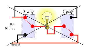
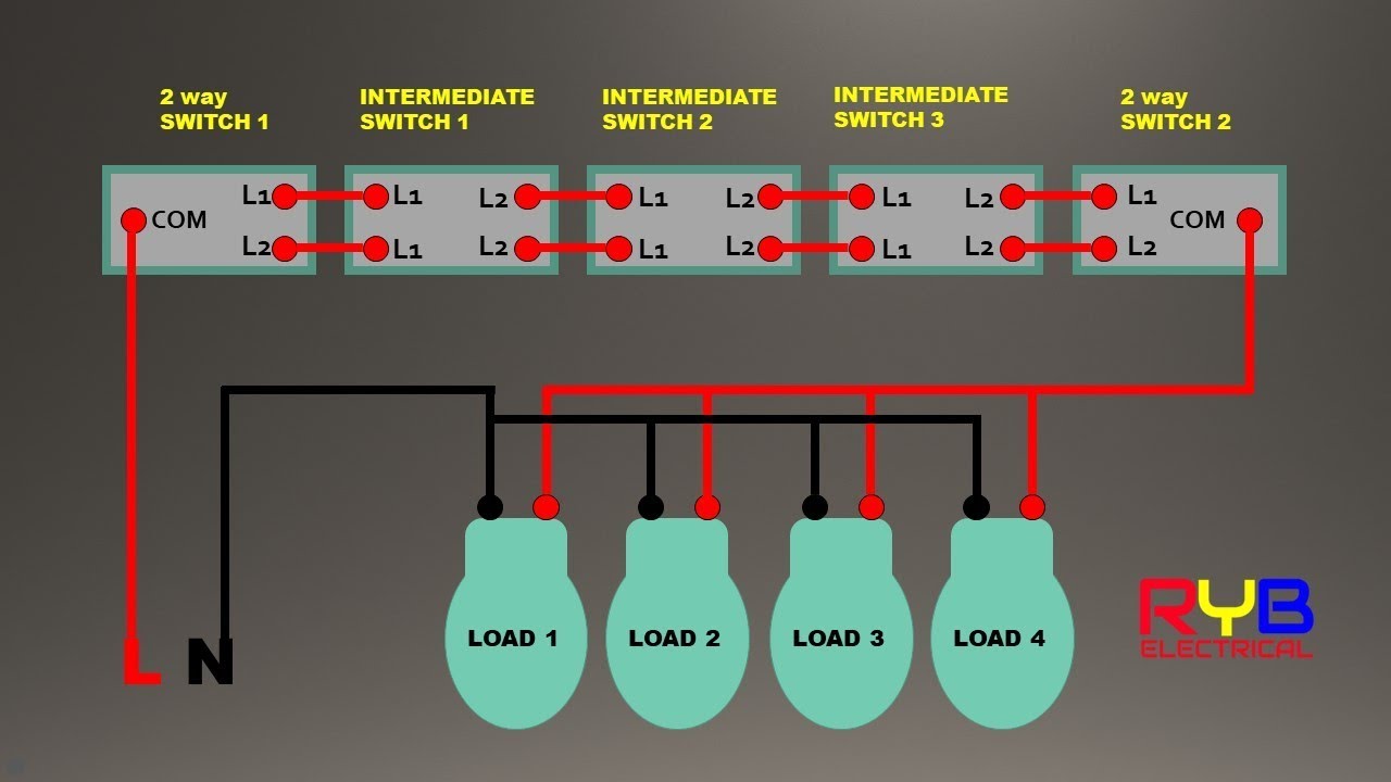
In one switch position the com terminal is connected to l1. Wall switches used to control ceiling light fixtures or other fixtures come in three types. Wires consisting of a line a load a neutral a pair of travelers and two 3 way switches. If your 3 way light switch 2 is connected between the power supply and the light fixture as is most common. Once youre done youll be able to control a light from two switches. The diagram below is based on the video you watched above.
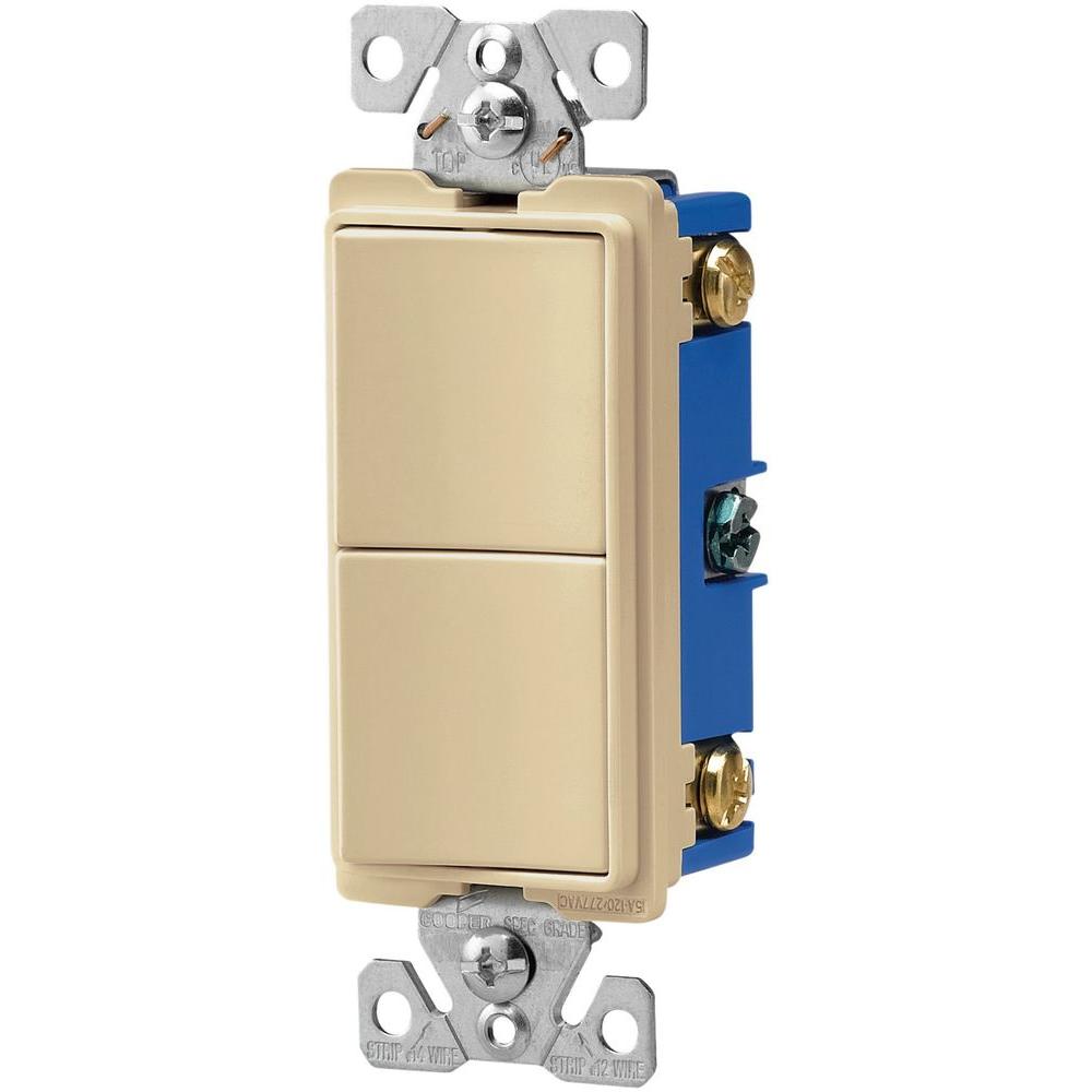
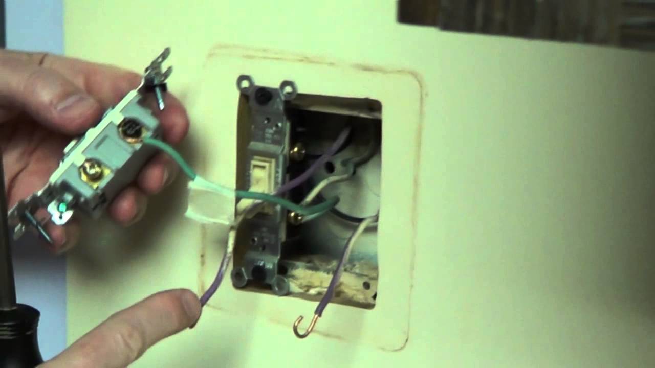
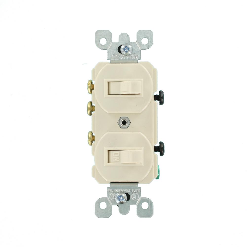
The black screw on a 3 way switch diagram is for the continuous hot wire that comes from the circuit. If you are trying to troubleshoot a 3 way switch operation then you will need to identify the function of each wire. With these diagrams below it will take the guess work out of wiring. A two way light switch is a simple single pole changeover switch with three terminals. Three wire cable runs between the switches and the outlet. A double pole switch allows you to control two separate circuits using the same switch while a three way switch allows you to control a single circuit from two different locations.
This story features diagrams that show how to wire 3 way switches. A double pole three way switch is able to integrate both of these functions into one. If you have any problems with these switches it may be best to call an electrician. 3 way switch wiring diagram. Most common is the single pole switch the type used to control a light fixture from a single locationthe next most common is the three way switch which is commonly used to control a light fixture from two different locations. Finish your work and test.
Take a closer look at a 3 way switch wiring diagram. What is the black screw for on a 3 way switch diagram. This circuit is wired the same way as the 3 way lights at this link. The existing 2 wire black and white romex can still be used to connect a 3 way switch 2 and the light fixture. See alternate 3 way switch wiring configuration for another way 3 way switches may be wired. Unfortunately not all 3 way switches are wired the conventional way.
In the other switch position it changes over so that com is connected. 3 way switched outlet wiring. These are typically labelled com l1 and l2 some may label the l1 and l2 positions as 1 way and 2 way. A 3 way switch wiring diagram is a simple drawing showing how to connect the wires to each of the four screws on the 3 way switch. All three way switch and 2 way switch wiring diagrams have the same basic components.
Gallery of 2 Pole 3 Way Switch Diagram