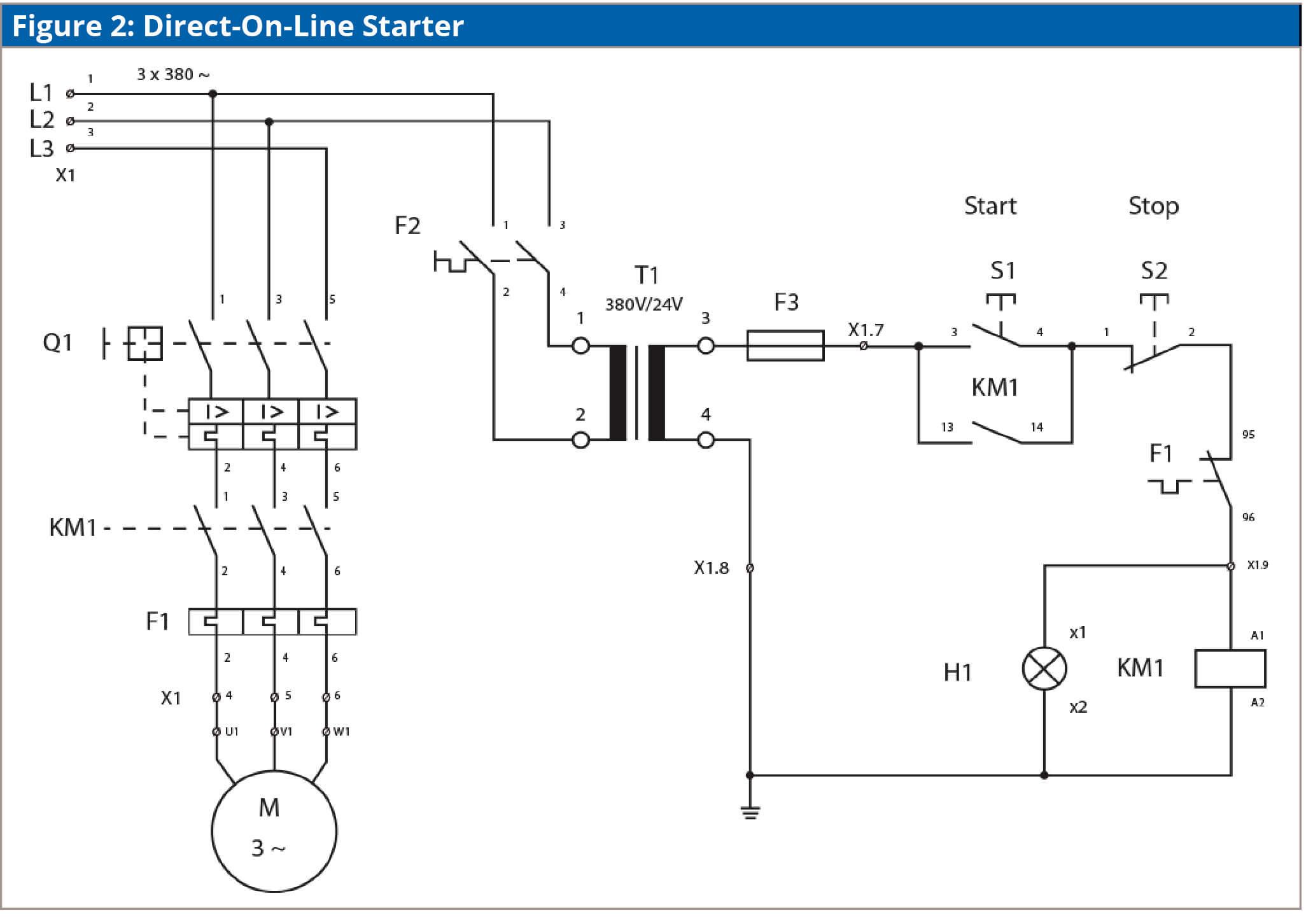
Motor control circuits gt. This surge current reduces as the motor accelerates up to its running speed.
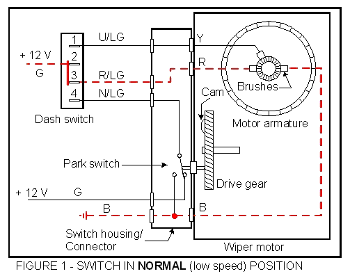
Lucas 2 Speed Windshield
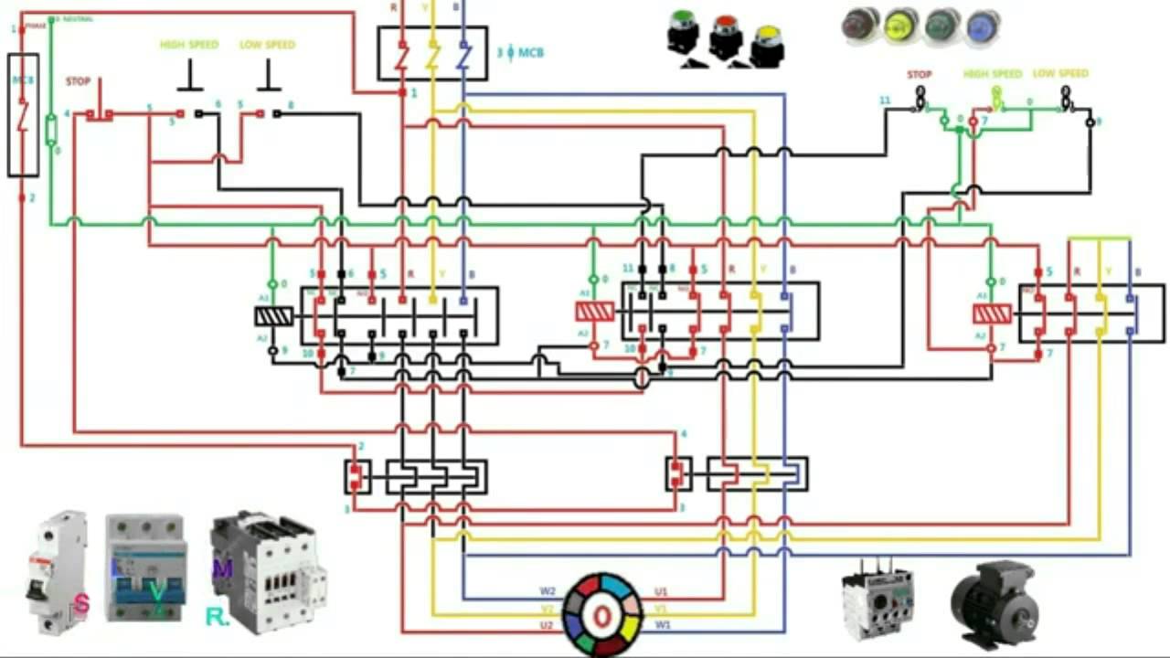
2 speed motor starter wiring diagram. Here is a picture gallery about two speed starter wiring diagram complete with the description of the image please find the image you need. It will also serve as a useful aid where simple wiring systems are to be studied. 2y connection three two with two speed starter wiring diagram image size 890 x 696 px and to view image details please click the image. Two speed motor wiring basics since a two speed motor relies on different coils to produce different speeds there are usually two input wires. Additionally the low speed coil is typically supplied by a red wire while the high speed coil is fed by a black wire. When the stator windings of an induction motor are connected directly to its 3 phase supply a very large current 5 7 times full load current flows initially.
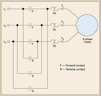
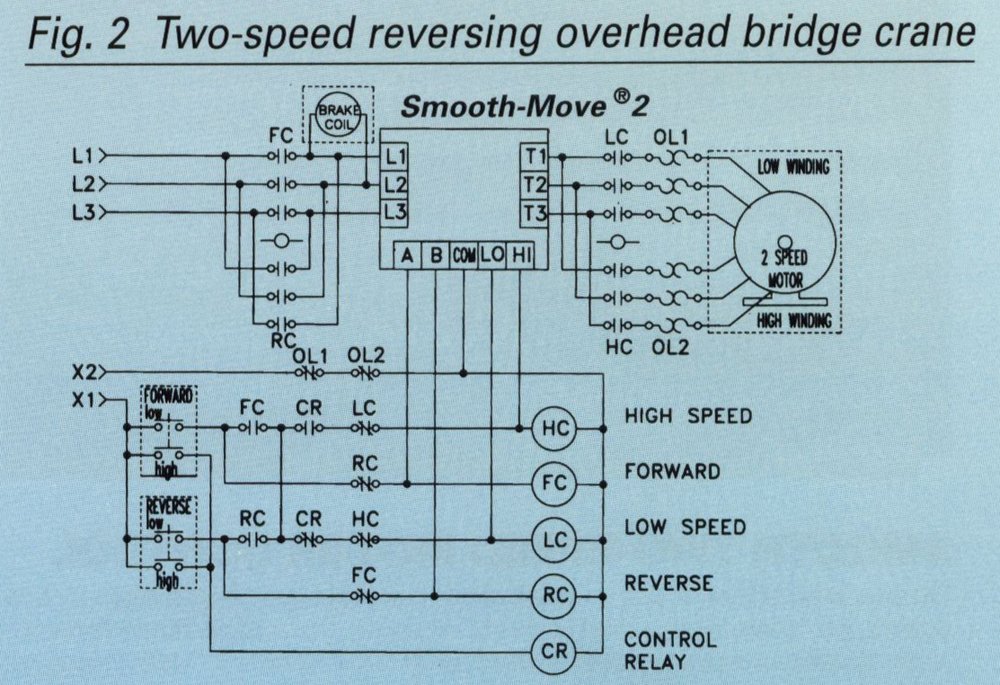
Wiring diagrams ww introduction this booklet has been prepared as a guide to some of the useful ways allen bradleys manual and magnetic across the line starters may be applied. Typical wiring diagrams diagrams are helpful in wiring up systems two speed manual motor starter is designed for starting protecting small single phase two speed ac fan motors 3 phase 2 phase 3 wire two speed starter bulletin 609ts sizes 0 1 3 phase 2 phase 3 wire for separate. When applying these diagrams it is well to remember that the features described in several diagrams may be combined into one to produce another useful way of applying allen bradley equipment. Two speed motors with 2 separate windings dual winding high speed red leads red leads black leads black leads m 3 single speed only 3ø wiring diagrams u1 red v1 yellow w1 blue thermal contacts tb white l1 l2 l3 n e codes. In many instances the low and high speed coils share an external wire. Multi speed 3 phase motor 3 speeds 1 direction power control diagrams one line diagram of simple contactor circuit.
As you become familiar with the diagrams. Several other combinations are possible in north america and other countries and are easily derived from the methods shown in this document. Auxiliary contacts 53 54 wiring diagrams 55 57 gi 20. Kindly email me the diagrams for star deltor and direct online for a 3speed 1directon 3ph motor have two of them in a bow cutter. A motor starter is a combination of devices used to start run and stop an ac induction motor based on commands from an operator or a controller. One contactor burnt for high speed and a replced contactor does not engange originally the coils re fed with a nutural and the one i replaced is only working with a phase.
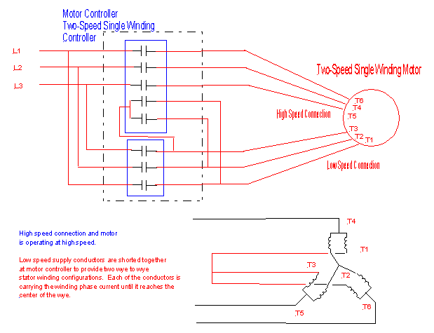
Three phase electrical wiring installation in home iec nec. Diagram dd4 low speed low speed u1 u1 v1 v1 w1 w1 u2 u2 v2 v2 w2 w2 l1 l1 l2 l2 l3 l3 e e high speed red leads red leads black leads black leads diagram dd3 two speed motors in dahlander connection tapped winding overload lo speed contactor hi. In north america an induction motor will typically operate at 230v or 460v 3 phase 60 hz and has a control voltage of 115 vac or 24 vdc. Induction motors started with direct on line dol starter. Please help how to go about this.
Gallery of 2 Speed Motor Starter Wiring Diagram