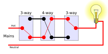
The hot from the power source cable c1 connects to the common terminal of the first 3 way switch sw1 and the neutral is spiced in the switch box sb1 through to the second 3 way switch sw2 via the 3 wire cable cable c2 that also carries the travelers that connect the two switches where it is spliced through to the first. As you can see in the schematic diagram of 2 way switch circuit below the common of both the switches are short circuited.
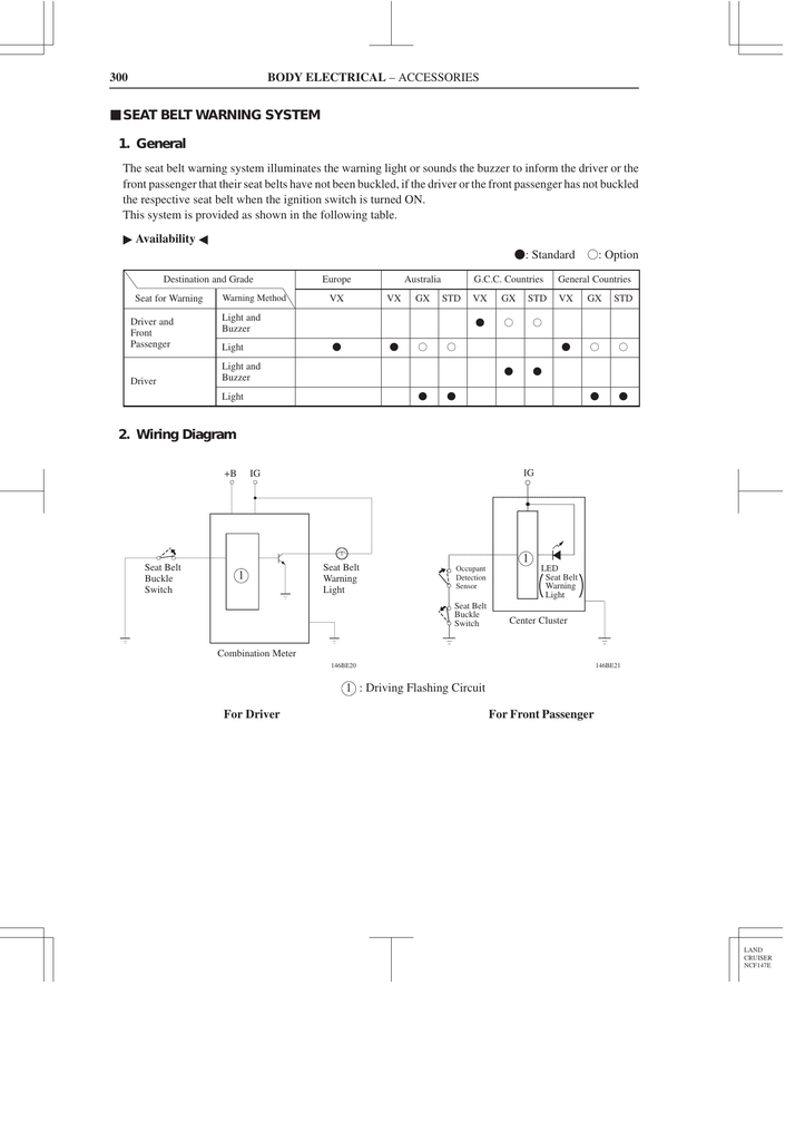
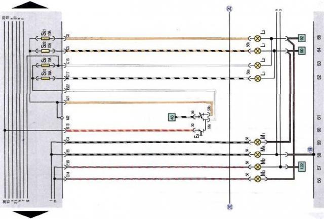
Seat Belt Warning System 1 General 2 Wiring Diagram
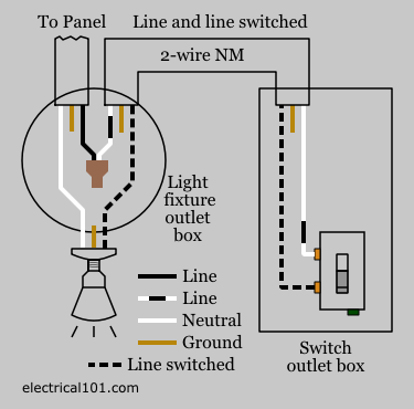
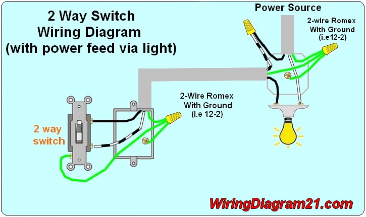
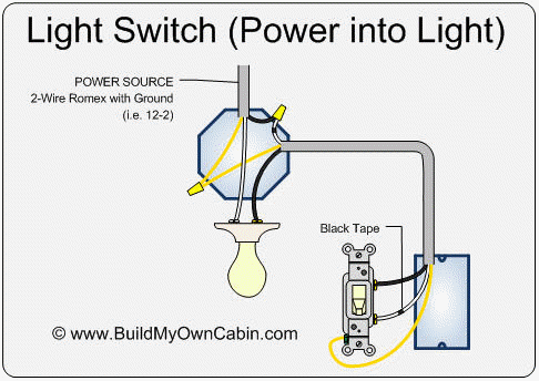
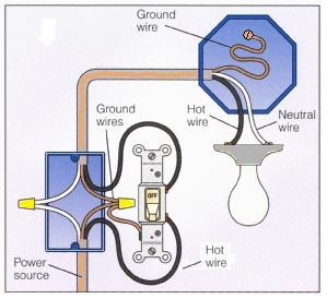
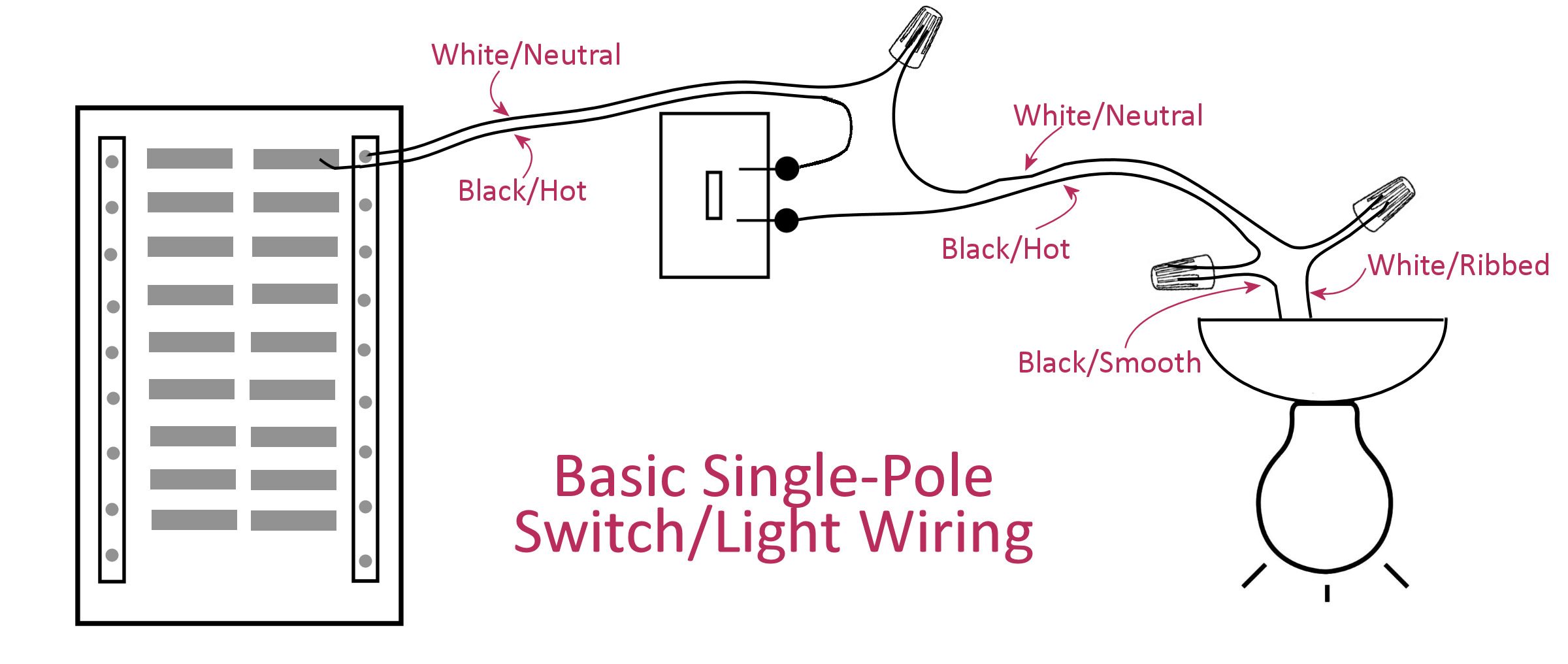
2 wire light switch diagram. Single pole switch diagram 2 this switch wiring diagram shows the power source starting at the fixture box. This light switch wiring diagram shows the power source starting at the switch box. The electrical symbol indicates where power enters the circuit. Single switch wiring diagram 2 wiring a single pole switch. Two way switch lighting circuit diagrams. A 2 way switch wiring diagram with power feed from the switch light.
At the light it connects to the neutral terminal. If you need to know how to wire a two way switch then this is the place to start. Wiring a single pole light switch. Here is a picture gallery about 2 wire light switch diagram complete with the description of the image please find the image you need. By wiring a 2 way switch the circuit below shows the basic concept of electricity flow to the load. The source neutral wire is spliced to the neutral on the receptacle half of the combo device and to the white cable wire running to the light.
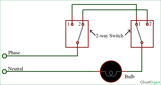
This is a completed circuit. Pin1 of both the switches are connected with the phase or live wire and pin2 of both the switches are connected with the one end of the lamp. The white wire of the romex going to the switch is attached to the black line in the fixture box using a wirenut. The other end of the lamp is connected with neutral line of ac power supply. This light switch wiring diagram page will help you to master one of the most basic do it yourself projects around your house. The electricity flows from the hot wire black through the 2 way switch shown in off position and then to the light and returns through the neutral wire white.
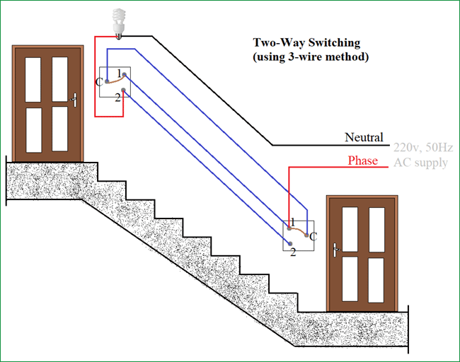
This site is merely. Electrical wiring diagrams with 2 wire light switch diagram image size 800 x 600 px and to view image details please click the image. Here we have multiple lights controlled by 3 way switches. Your example shows 2 wire romex but most romex i have seen has three wires one white one black and an un shrouded copper ground wire. Here is our selection of two way switch circuit diagrams. What is the correct connection for this ground wire.
Lets assume the load you are controlling is a light. You will see that there is a hot wire that is then spliced through a switch and that then goes to the hot terminal of the light. Wiring diagrams for light switches. 2 way light switch circuit wiring diagrams. Two wire cable runs from the combo to the light fixture and the switch output is connected to the black wire running to the fixture hot terminal. Hey doing it yourself is great but if you are unsure of the advice given or the methods in which to job is done dont do it.
The power source comes from the fixture and then connects to the power terminal.
Gallery of 2 Wire Light Switch Diagram