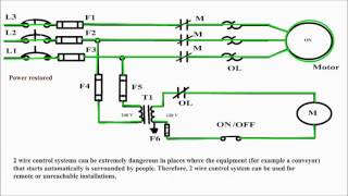
2 wire control vs 3 wire control. If the single pole switch is toggle closed the motor starter will start and stay on for as long as the single pole.

Resolved Problem With Using Xtr117 Amplifiers Forum
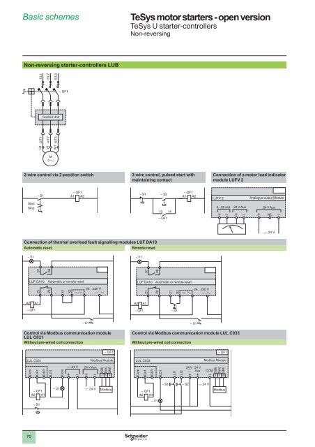
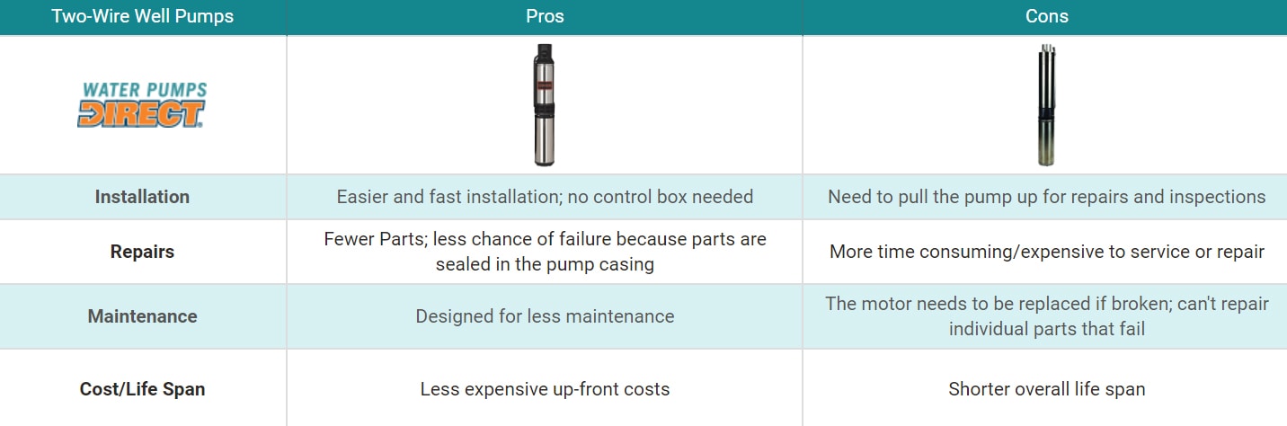
2 wire vs 3 wire control. A 3 wire pump actually has four wires going into the control box and 4 wires going to your pump. Benefits of a 2 wire over a 3 wire pump. One example of a 3 wire lighting system. In both circuits shown above the reverse command can be ignored if not necessary for the application still the same circuit is applicable for 2 wire and 3 wire control. The two wire circuit in configuration 2 operates as follows. When to use 2 wire control and when to use 3 wire control.
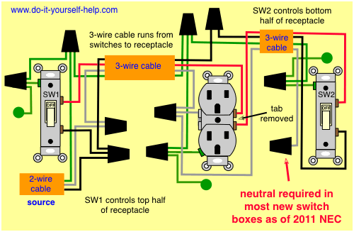
2 wire circuit a 2 wire black and white with the ground cable will be used for one hot and one neutral or one circuit. An example of a 3 wire lighting circuit is shown in figure 2. It means if the stop command is provided separately it is called 3 wire control and if separate stop command is not provided separately it is called as 2 wire control. Inside is the relay and start capacitor. 2 wire construction is the least accurate of the 3 types since there is no way of eliminating the lead wire resistance from the sensor measurement. Below is a control box.
2 wire rtds are mostly used with short lead wires or where close accuracy is not required. What is the difference between 2 wire rtd 3 wire rtd. In h2os experience we find the 2 wire pumps to be more reliable and robust. Ironically a 2 wire pump actually has three wires coming from your home to the pump two hot and one ground. The 3 wire system is less common than the 2 wire system it includes a neutral at the switch as well as the live and switched live wires. 2 wire control and 3 wire control.
If the single pole switch marked s1 is left open then the liquid level switch in the circuit will now be the control. 3 wire circuit a 3 wire circuit black red white and the ground cable can be used for feeding two circuits that will share the neutral and ground wire.
Gallery of 2 Wire Vs 3 Wire Control