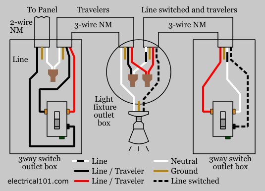
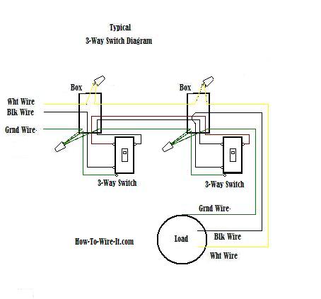
A 3 wire nm connects the traveler terminals of the first and second 3 way switch together. Wiring of 3 way light switches is certainly more complicated than that of the more common single pole switch so follow our 3 way switch wiring diagram.

Sm 7023 Wiring Switch Circuit
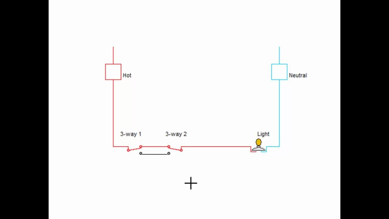
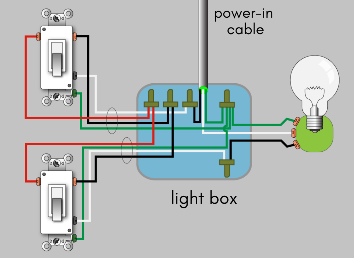
3 way switch schematic. A 3 way switch wiring diagram is a simple drawing showing how to connect the wires to each of the four screws on the 3 way switch. Travelers can be wired in either of the below examples. What is the black screw for on a 3 way switch diagram. You can observe how the schematic look of 3 way light switch. Toggling either of the 3 way switches will cause a closed path to open or an open path to close. Either way complete these five steps for 3 way light switch wiring.
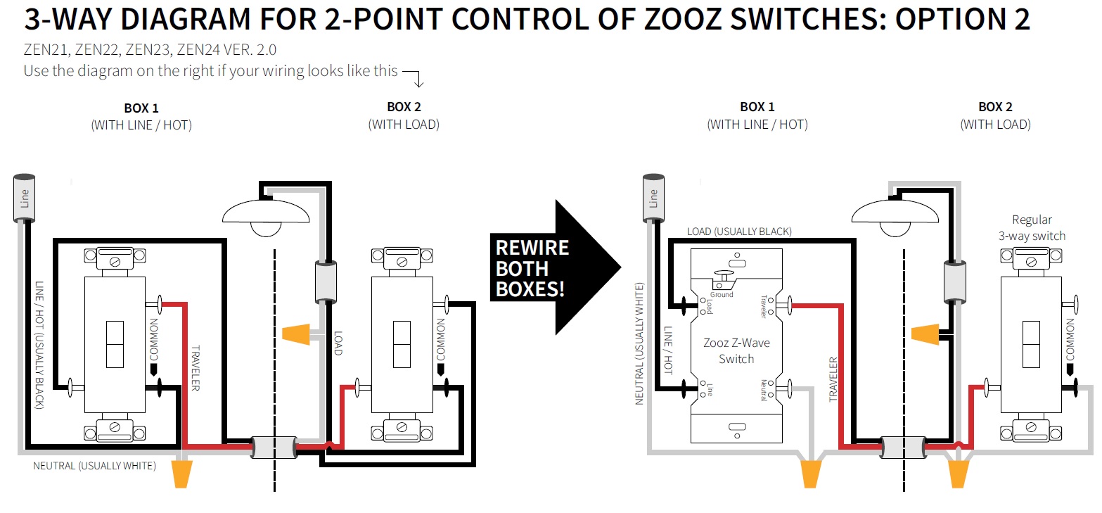
Pick the diagram that is most like the scenario you are in and see if you can wire your switch. Add an electrical box for the second 3 way switch in the basement. If you are trying to troubleshoot a 3 way switch operation then you will need to identify the function of each wire. These wiring diagrams are available in this post to be used as references and illustrations on how to set a 3 ways switch wiring. 3 way switch wiring diagram. The basic 3 way switch wiring diagram this is the most common and the easiest wiring diagram to follow of any of the wiring diagrams for a 3 way switch circuit.
Its likely youll also need to replace the. The white wire becomes the energized switch leg as indicated by using black or red electrical tape. The black line wire connects to the common terminal of the first 3 way switch. Its likely youll also need to replace the. Turn off the correct circuit at your electrical panel. It reveals the components of the circuit as streamlined shapes and the power and also signal links in between the gadgets.
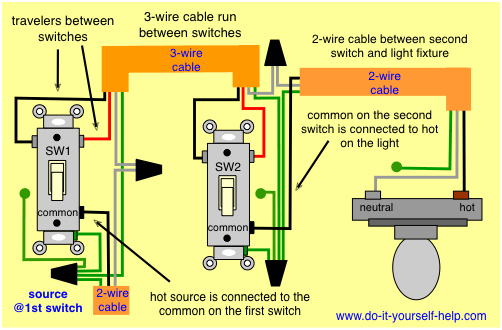
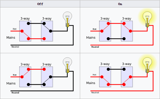
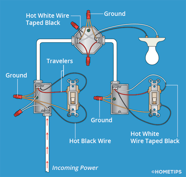
Wellborn assortment of 3 way switch wiring schematic. 3 way switch diagram 2 above shows the electricity source starting at the fixture. Left switch is toggled down to create a continuous path light is on. Typical 3 way switch wiring nm cable in the 1st diagram below a 2 wire nm cable supplies power from the panel to the first switch box. This wire diagram shows the wiring for source power into the first three way switch then 3 wire cable to the next 3 way light switch and then on to the light or light fixtures. Take a closer look at a 3 way switch wiring diagram.
September 4 2019 by larry a. With these diagrams below it will take the guess work out of wiring. Wires consisting of a line a load a neutral a pair of travelers and two 3 way switches. The white wire of the cable going to the switch is attached to the black line in the fixture box using a wire nut. Right switch is toggled up to open the path light is off. All three way switch and 2 way switch wiring diagrams have the same basic components.
The diagram below is based on the video you watched above. A wiring diagram is a streamlined conventional pictorial depiction of an electrical circuit. This might seem intimidating but it does not have to be.
Gallery of 3 Way Switch Schematic