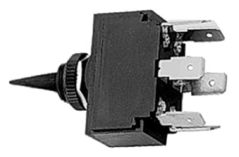
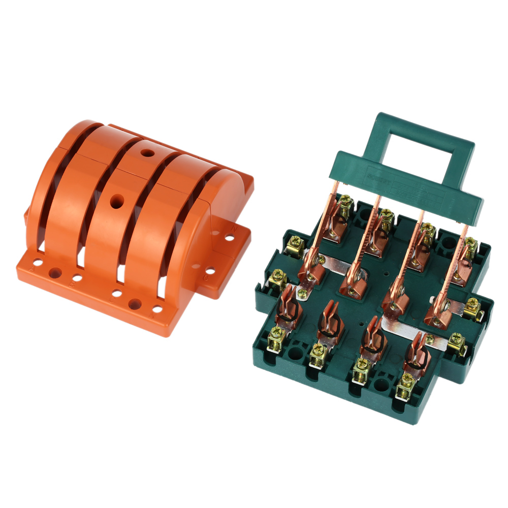
Look at picture 11 and 12 it consists of two common input terminals c e and both mechanically tied together to operate in the. Double pole double throw toggle has 2 input terminals and 4 output terminals.

A Double Pole Double Throw Toggle Switch B Electrical
4 pole double throw switch schematic. You can see above how a double pole double throw switch can allow a circuit to be in 1 of 4 modes. Here pole indicates individual input circuit and throw indicates the output circuit. Double pole double throw 3pdt three pole double throw 4pdt four pole double throw. Poles and schematics single pole double pole three pole four pole. Single pole one circuit controlled by the switch. Double pole double throw switch dpdt circuit.
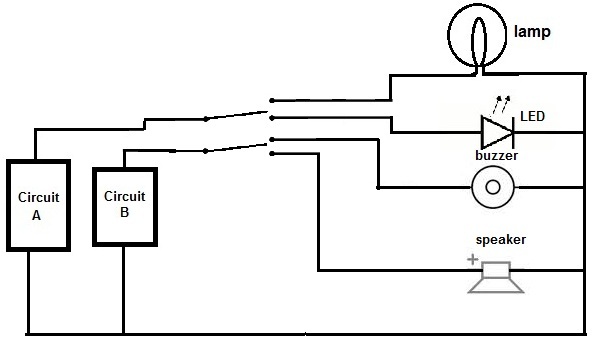
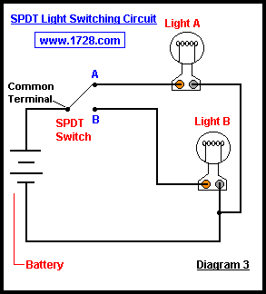
Special circuits three throw on on on 3. Below is an example of a circuit which utilizes a double pole double throw switch. Double pole double throw switch dpdt circuit. Throw single throw switch on none off double throw switch on none on throw number of electrical circuits within a pole. 1 pole double throw switch 12 volt single pole double throw switch 12 volt single pole single throw switch 120 volt double pole double throw switch 120v single pole. You can see above how a double pole double throw switch can allow a circuit to be in 1 of 2 modes.
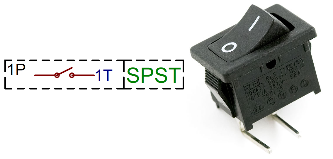
When the dpdt switch is switched one way flipped upward in the diagram the lamp and buzzer are both on while the. Below is an example of a circuit which utilizes a double pole double throw switch. Double pole two independent circuits controlled by the switch which are mechanically linked. Circuit a is connected to a lamp and an led. When is the switch is one way the lamp is on and the led is off. Switch reference guide spst spdt dpst dpdt sp and dp refer to single pole and double pole st and dt refer to single throw and double throw.
Fig 12 dpdt terminal diagram.
Gallery of 4 Pole Double Throw Switch Schematic
%2C445%2C291%2C400%2C400%2Carial%2C12%2C4%2C0%2C0%2C5_SCLZZZZZZZ_.jpg)