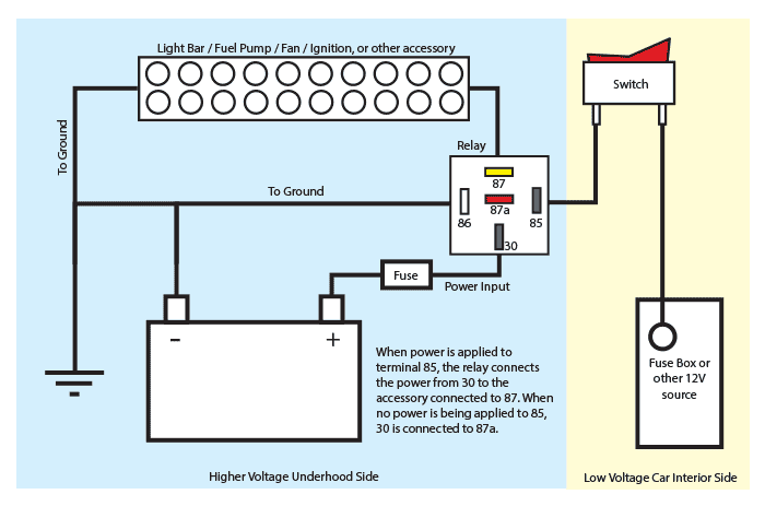
A relay can be used to power a new circuit with very little added current draw on the original wiring. See my switch terminology page for more on contact arrangements if you need to.
Using Relays In Automotive Wiring
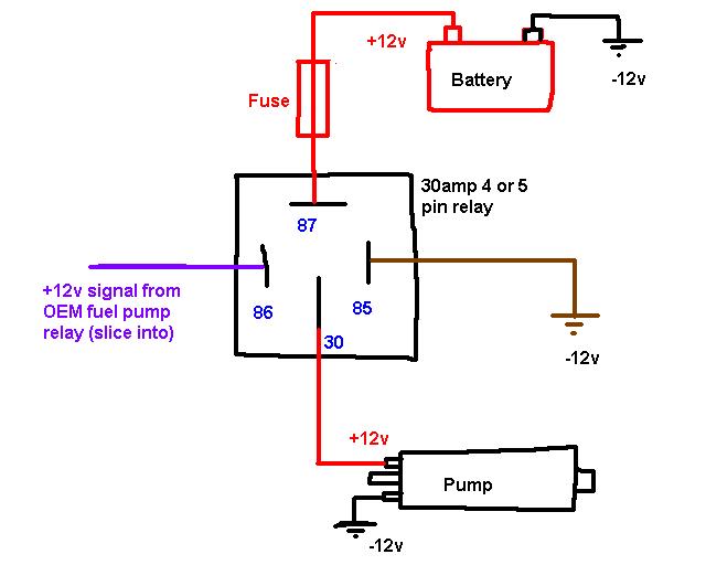
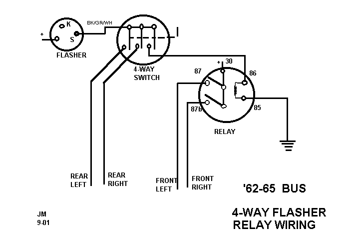
4 way relay wiring. The white wire is marked black at each end to mark it as hot. If you want a normally open relay you will wire to 87. Realizing that 85 and 86 are the coil pins. 40 amp 4 pin relay wiring diagram on 40 images. I never write reviews but i figured this would be a good one since i researched hi and low to figure out how to wire. In this video i show you how to wire a 12 volt automotive bosch style relay.
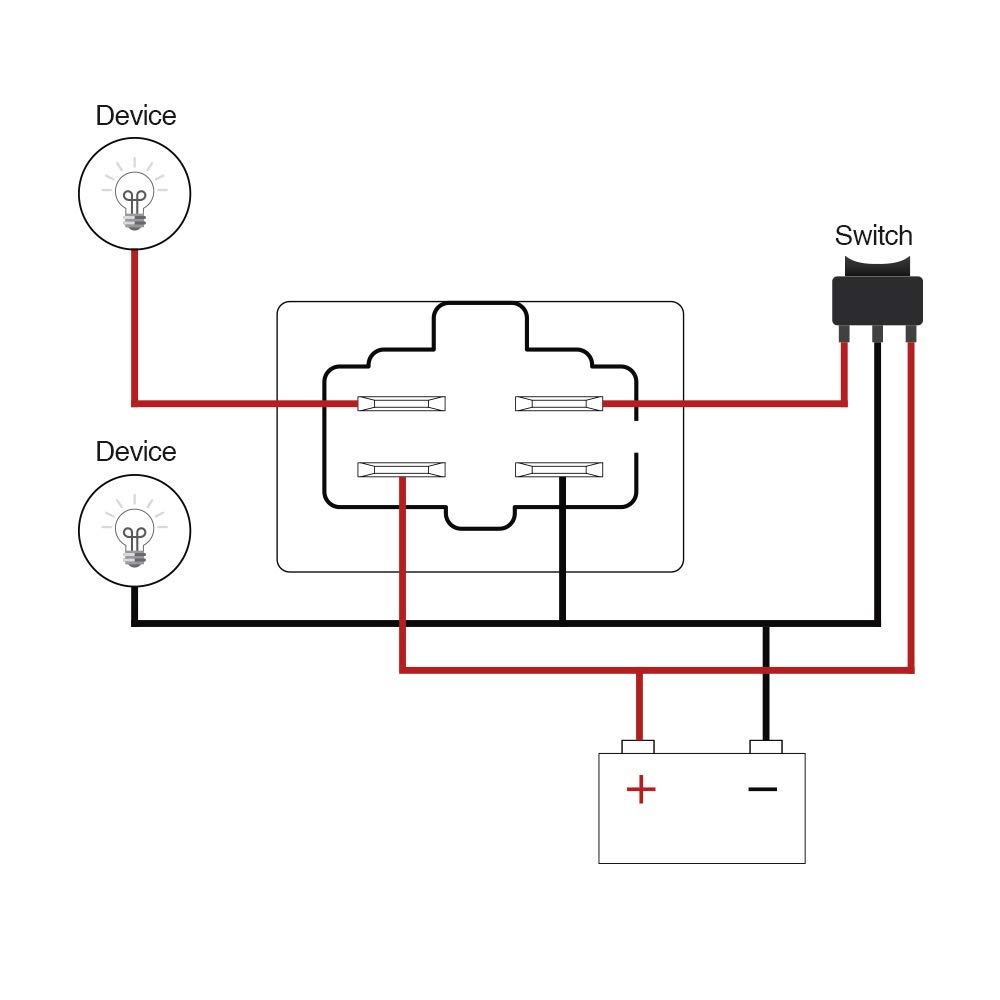
This 4 pin relay comes with no labeling or wiring diagram. Using a relay can also shorten the distance that high current wiring needs to run. Wiring with a relay allows the power to run straight from the battery through the relay mounted nearby directly to the lights. The black wire running to the 4 way switch is connected to the hot terminal on the light and at the switch box its spliced to the black wire from the common on sw2. Connect relay terminal 87 to the vehicle body or battery negative terminal. So when wiring up these relays the coil wires will connect to pins 2 7 on the socket.
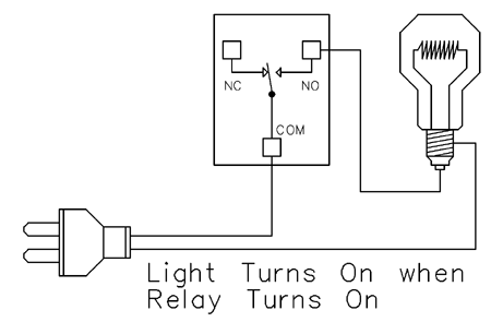
Spst 4 way 40a 12v relay wiring pin out diagram what is a relay. I go over what each contact of the relay is for and how to understand the schematic that is. Instructions for wiring a standard automotive relay with descriptions of the pin out and the schematic. If more than three switches are needed simply place more 4 way switches between the three way switches. This video covers both 4 and 5 pin 12vdc relays. Pins 8 6 as normally open pins 8 5 as normally closed.
The red and white are used as travelers between the 4 way and sw2. Although most relays are labeled at the bottom you can always find the 30 pin set perpendicular to pins 87 and 87a for easy identification to the power source. See below for an example of a relay wiring diagram. Pins 1 3 as normally open pins 1 4 as normally closed. If you want a normally closed relay you will want to wire to 87a. The difference between a 4 and 5 pin relay is that a 4 pin relay is used to control a single circuit whereas a 5 pin relay switches power between two circuits.
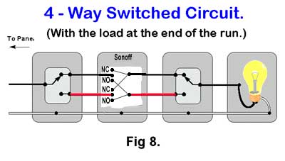
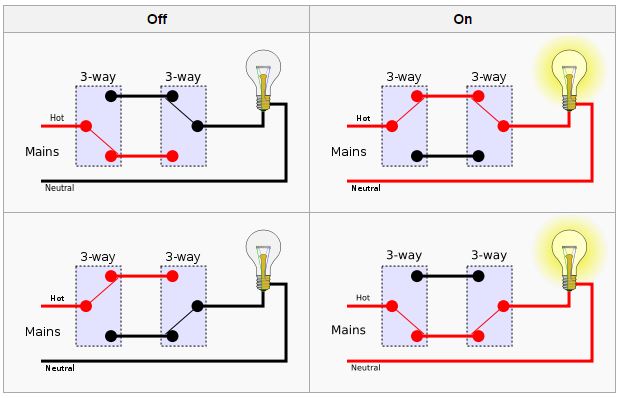
Output for a relay. These layouts are shown on the two 5 pin relays below. Use a piece of 18 gauge primary wire with a solder less female spade. 4 pin relay 4 pin relays use 2 pins 85 86 to control the coil and 2 pins 30 87 which switch power on a single circuit. 4 way switch wiring 4 way switches provide switching from three or more locations. The interior mounted switch only draws minimal power though the interior fuse block to activate the relay.
The other pole has. As you will see most 4 way switch wiring is placed between the wiring of two 3 way switches therefore a 4way switch is installed with two 3way switches. Buy relays pigtails and kits here.
Gallery of 4 Way Relay Wiring