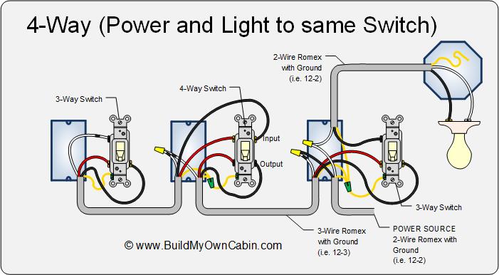
To view it at full size click on the diagram. This 4 way switch diagram 2 shows the power source starting at the fixture.
Can I Put Two Red Wires Together With A Black Wire In Ceiling
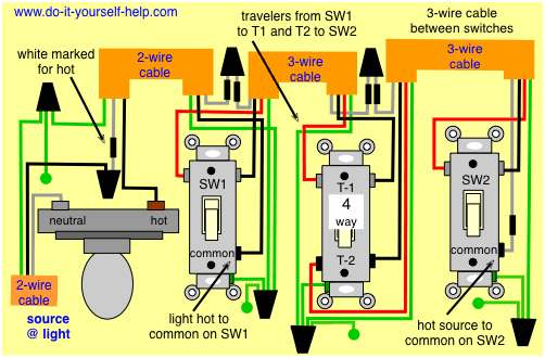
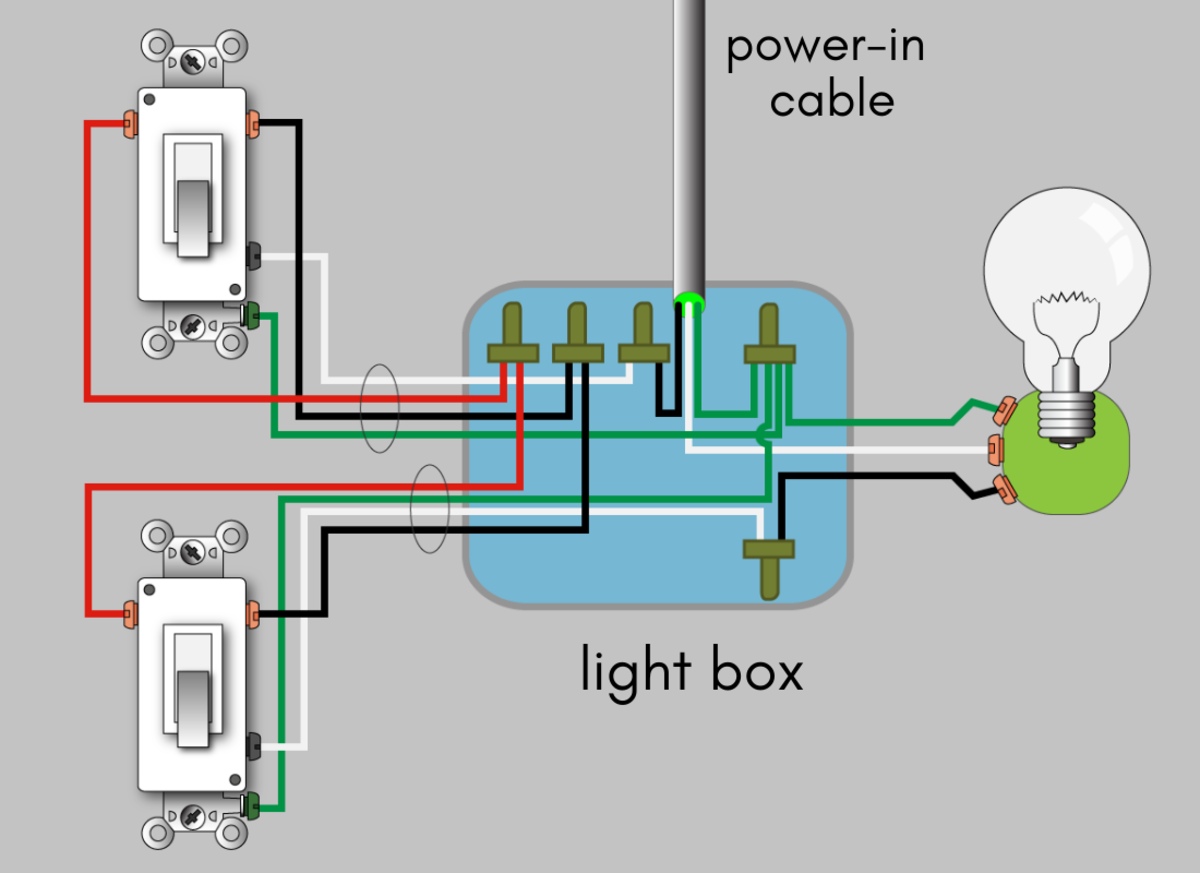
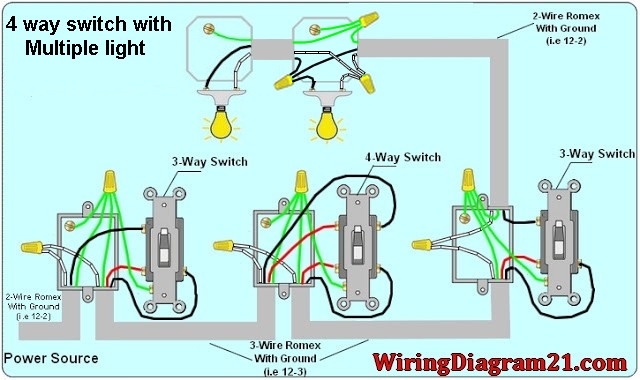
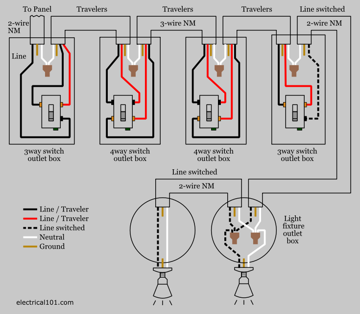
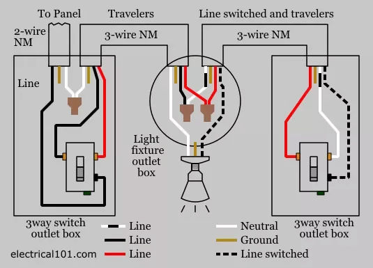
4 wire light switch wiring diagram. The electrical switch box that contains the line and load wires may need to be bigger than the other switch boxes especially if there are other wires going into the. 4 way switch wiring with light first this diagram illustrates wiring for a 4 way circuit with the electrical source at the light fixture and the switches coming after. I have a few of the most common ways in wiring a 4 way switch to help you with your basic home wiring projects. Note that a 3 conductor cable is often used for connecting 3 way and 4 way switches to each other containing black white and red conductors. A wiring diagram is a streamlined standard pictorial depiction of an electrical circuit. The third wire the red will not be switched at the 4 way location but passes to the final 3 way switch.
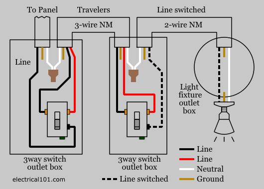
The hot and neutral terminals on each fixture are spliced with a pigtail to the circuit wires which then continue on to the next light. 4 way switch wiring diagrams this 4 way switch diagram 1 shows the power source starting at the left 3 way switch. Circuit electrical wiring enters the switch box. Smarthome sells many types of smart switches and plugs. This diagram is a thumbnail. Do you need a 3 way switch wiring diagram.
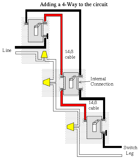
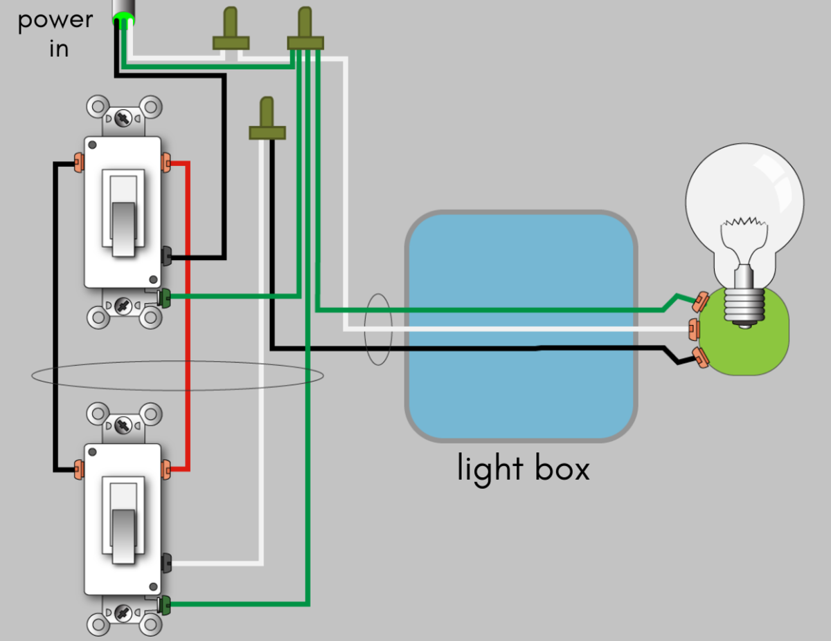
Below is another method for wiring 4 way switches. Switch wiring shows the power source power in starts at the switch box. Collection of 4 wire ceiling fan switch wiring diagram. This diagram illustrates wiring for one switch to control 2 or more lights. When wiring in the 4 way switch it is most simply described as simply cutting the two traveler wires the two wires that go between the two 3 way switches and terminate on each switch and putting two wires from one switch on the top two terminals of the 4 way switch while putting the other two wires from the other switch on the bottom two terminals. For complete instructions on wiring a basic 4 way switch see our wiring a 4 way switch article.
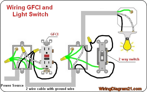
The black wire power in source attaches to one of the switch screw terminals. These two wires are the travelers to the 4 way switch. The source is at sw1 and 2 wire cable runs from there to the fixtures. Power from light fixture to light switch. The 4 way is used when you want to control the light or lights from two or more locations. Two wire cable is run from the light to sw1 and 3 wire cable runs between the three switches.
Click here to access note. Featuring wiring diagrams for single pole wall switches commonly used in the home. Multiple light wiring diagram. More 4 way switch wiring diagrams four way switch wiring schematic. In general practice the diagram above is most often used and is a good guide for wiring a new 4 way switch circuit. A 4 way switch wiring diagram is the clearest and easiest way to wire that pesky 4 way switch.
Explanation of wiring diagram 1. It reveals the elements of the circuit as simplified shapes and the power and signal connections between the tools. The white wire of the cable going to the switch is attached to the black line in the fixture box using a wirenut.
Gallery of 4 Wire Light Switch Wiring Diagram