8 pin and 11 pin pla relay ke connection lagbhag same hote hai bas 11 pin. Discover and save your own pins on pinterest.

Trouble Shooting Tips For Plug In Products
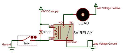
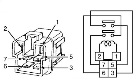
6 pin relay connection diagram. The relay srd 05vdc sl c is a single pole double throw spdt type relay. Thanks so much for your help peter. Ive included the two wires coming from the camera right side of the diagram. Purple and brown wires which i do want this circuit to closeconnect so the shutter will operate. Relays are generally used to switch smaller currents in a control circuit and do not. Click on the image to enlarge and then save it to your computer by right.
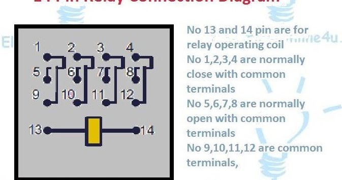
When a relay contact is closed there is a closed contact when the relay is not energized. Same as previous parts lets start with determining the relay coil pins using a multimeter. When a relay contact is open the relay is not energized. A wiring diagram is a streamlined conventional photographic depiction of an electrical circuit. Read relay diagram. Here we look at relay switch pin diagram and the different kinds of relay switches.
Please practice hand washing and social distancing and check out our resources for adapting to these times. 12 volt relay wiring diagram bosch relay wiring diagram 5 pole fresh 5 pin relay wiring diagram inspirational pin relay wiring. Light relay wiring diagram. Collection of 6 pin dpdt switch wiring diagram. Pin 1 1 toyota tacoma electrical wiring diagram to engine control module4 7 d to bulb check relay comb meter 27 628 4 b w 1 toyota tacoma electrical wiring diagram a 22 3e at 2 mt 2 acc ig1 st1 ig2 mt am1 b w 1 7am2 6 w r 22 w b 22 b w 20 3e 6 3e 4 ea1 21. 8 pin pla relay connection and pin diagram friends is video mai ham 8 pin pla relay ke connection discuss kar rahe hai.
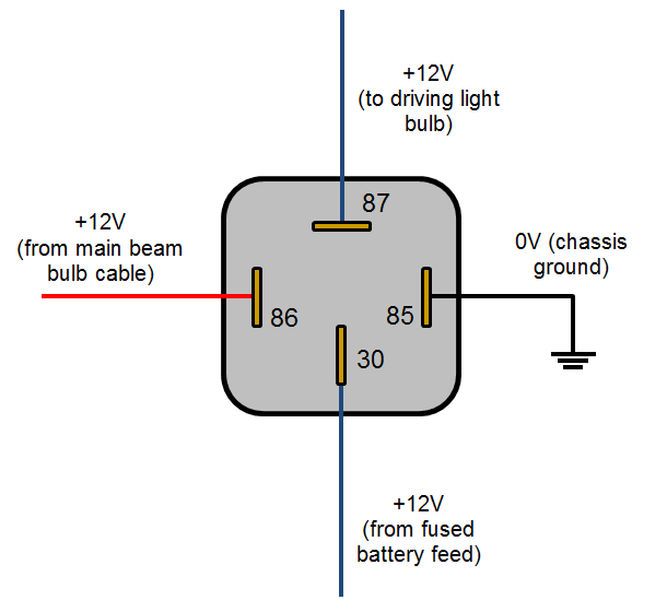
Assortment of 12 volt relay wiring diagram. Set the multimeter to resistance measuring mode with a scale of 1000 ohm since the coil resistance normally ranges between 50 ohm. Relays switches are used to open and close circuits electromechanically or electronically. Oct 14 2019 this pin was discovered by robert. That makes me think bottom right is normally open until voltage crosses the coil and creates a closed connection. Stay safe and healthy.
Oct 14 2019 this pin was discovered by robert. In either case applying electrical current to the contacts will change their state. This is just naming convention now i understand the proper function. Ac motor diagram start relay diagram 4 pin relay diagram auto relay diagram dpdt relay diagram automotive relay diagram 12 volt relay wiring diagrams reverse polarity relay diagram 7gfbcxdominik suessde. 6 pins relay trb 12vdc sb cl 1. Electrical symbols electrical projects.
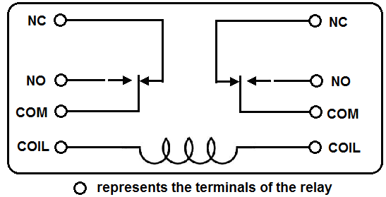
I realize that the relay im showing in this diagram may be an 8 pin but im imagining its a 6 pin with the same schematic as the relay image example here. It shows the elements of the circuit as streamlined forms and the power as well as signal links in between the gadgets. When i attach the live wire from the power source to the bottom right pin the live wire from load on a left pin and apply a voltage across the coil my leds turn on. Discover and save your own pins on pinterest.
Gallery of 6 Pin Relay Connection Diagram