Automatic water pump controller circuit fig. In the countryside water is very important.

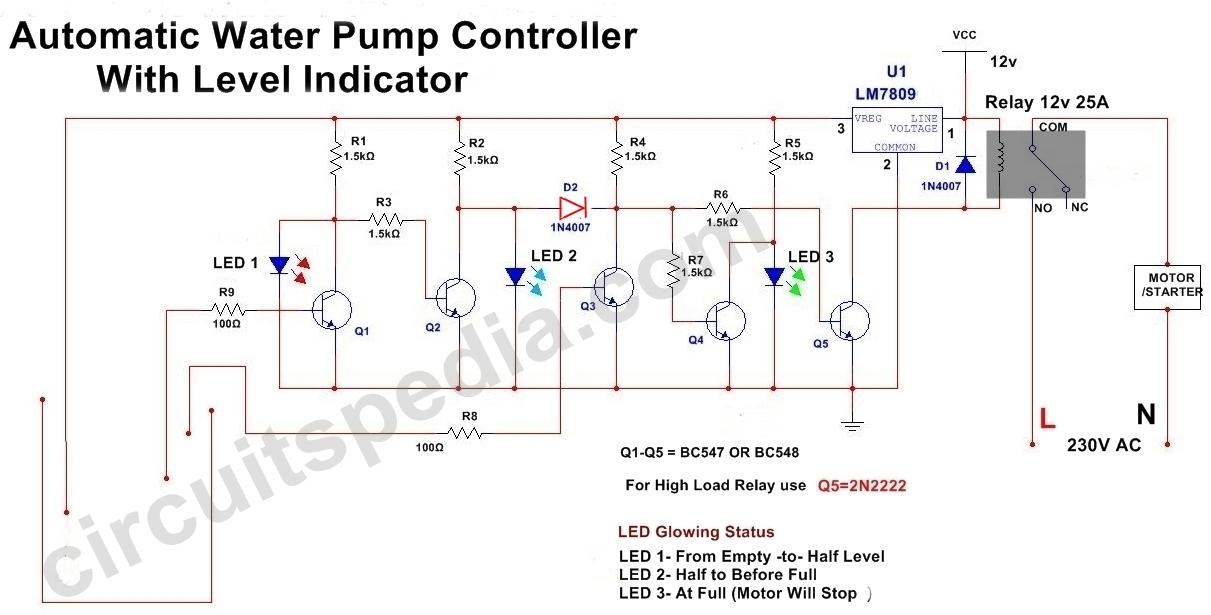
Automatic Water Pump Controller Circuit With Indicator
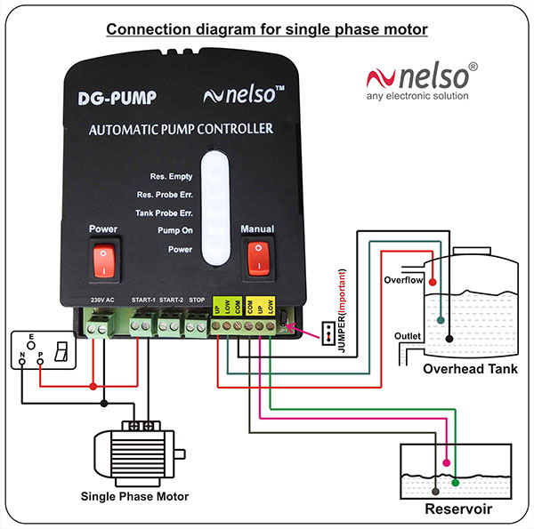
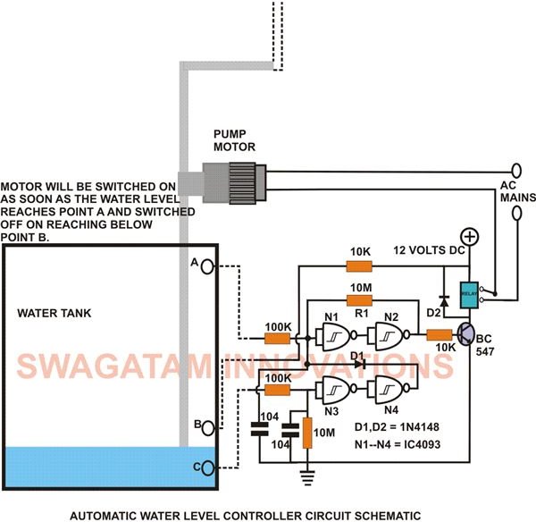
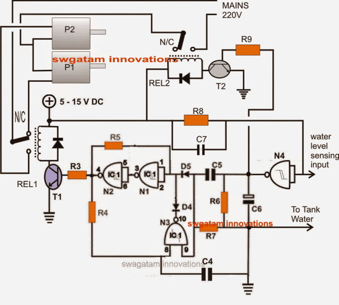
Automatic pump control circuit diagram. The module can be connected to a flow switch and to trip signals to automatically rotate the pump in case of equipment failure. The 12v dc power supply is given to probe c which is the limit for minimum water always stored in the tank. Star delta y δ 3 phase motor starting method by automatic star delta starter with timer. Here we have manipulated the flip flop inside the 555 timer ic. The module has unique flow switch delay timer adjustable 15s to 60s minimising the false alarms. This is an automatic water pump controller circuit diagram using an ne555 timer.
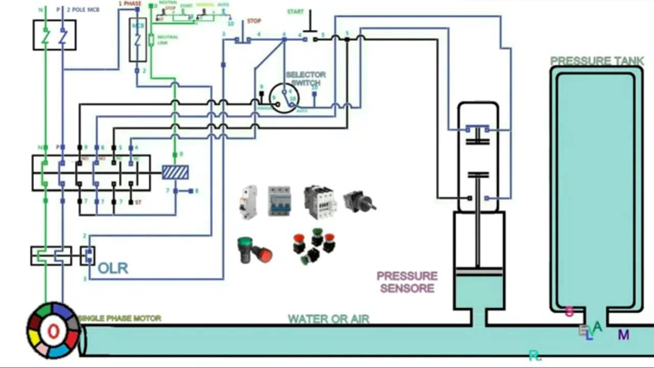
Need ckt diagram fr three motor having star delta starter on same mcc such that only 2motor can start simultaneously not 3rd one. Submitted by anonymous not verified on mon 11182013 1613. The timer in the circuit is used to time out c3 and time in c2 to understand it just identify the contact of the timer in the circuit u. Plc ladder diagram water level control pdf. Three phase motor connection stardelta without timer power control diagrams. Let us consider two reference probes a and b inside the tank where a is the lower limit probe and b is the upper limit probe.
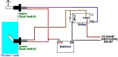
The main advantage of this water level controller circuit is that it automatically controls the water pump without any user interaction. They often use the pump automatically. The circuit will automatically switch on any water pump motor when the level of water in a tank reaches below from the required level and automatically switch off the pump after filling the tank. Three phase motor connection schematic power and control wiring installation diagrams. This diagram is for the circuit to empty a tank using two normally open float switches and a two pole changeover relay. The most to use the groundwater to dig as a pond and for the convenience.
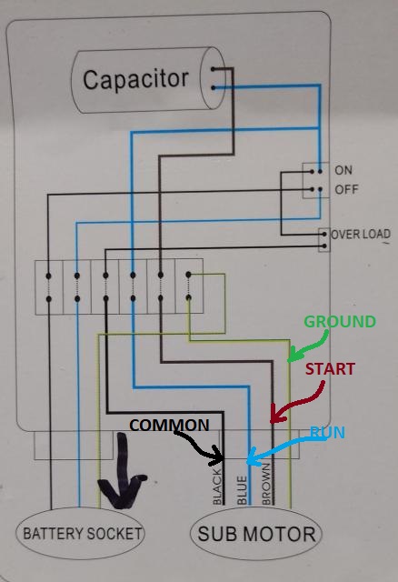
One set of relay. The bottom switch will be closed provided the liquid is above that switch point. Here is the complete guide step by step. Single phase submersible pump control box wiring diagram 3 wire submersible pump wiring diagram in submersible pump control box we use a capacitor a resit able thermal overload and dpst switch double pole single throw. How to create a pump control circuit to automatically empty a tank how to create a pump control circuit to automatically empty a tank. Please describe the the control circuit diagram of automatic star delta starter with timer for 3 phase motor.
The heart of this pump controller circuit is a ne 555 ic. 1 shows the controller circuit. The wiring connection of submersible pump control box is very simple. Our project consists of two water level sensors one fixed at the top and other at the. Automatic water pump controller circuit diagram here is a very useful project of an automatic water pump controller circuit. Motor power rating star or delta.
The liquid rises until the top float switch closes and energises the relay. The pmpco pumpfan change over module automatically rotates the lead load pump when the demand signal is applied.
Gallery of Automatic Pump Control Circuit Diagram