Check voltage on module with ignition off. Dual battery isolator wiring diagram dual battery isolator circuit diagram dual battery isolator switch wiring diagram dual battery isolator wiring diagram every electric structure is made up of various unique pieces.
Pac 80 Isolator Wiring Diagram H1 Wiring Diagram
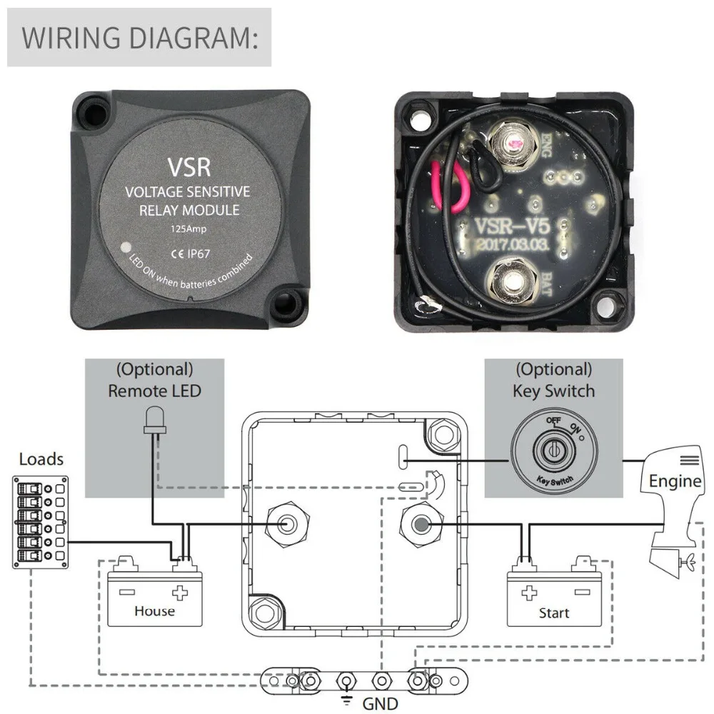
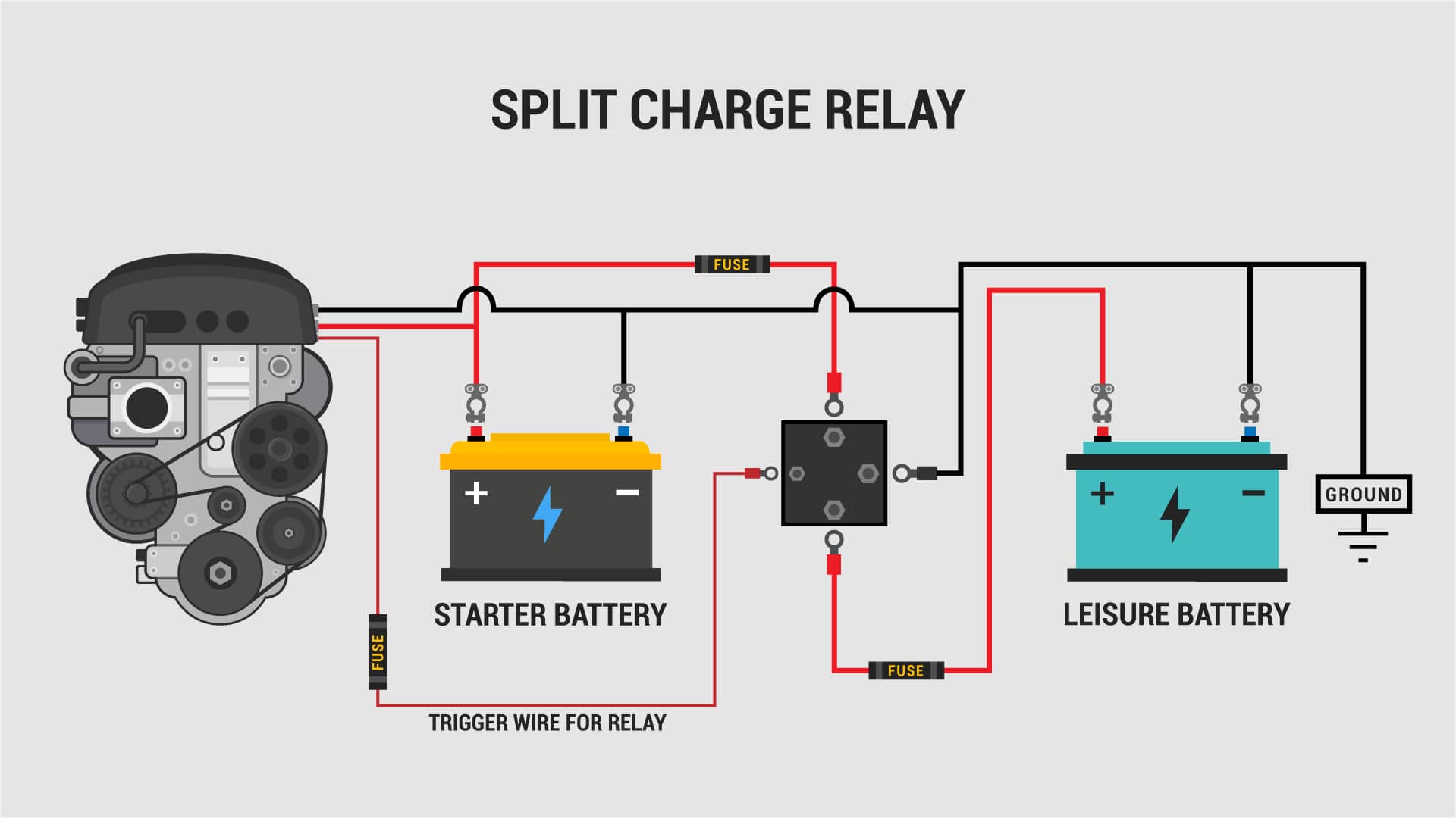
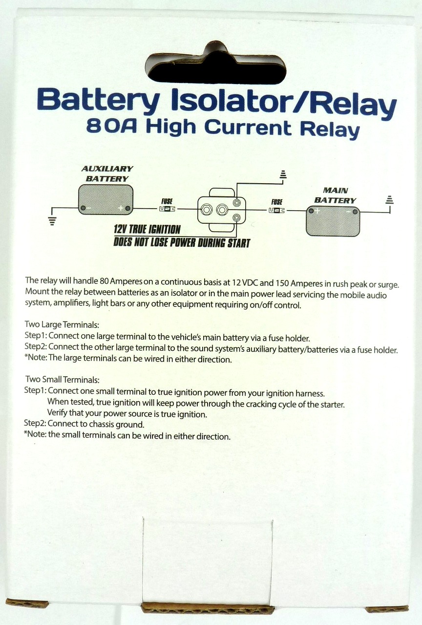
Battery isolator relay wiring diagram. If the drop is greater than 03 volts replacerelay. Each component should be placed and linked to other parts in particular way. The diode battery isolator. Inexpensive 12 volt smart battery isolator with 150 amps pass through and solid state control. Otherwise the arrangement will not work as it should be. Welcome to winnebago industries wiring diagrams.
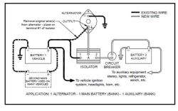
Direction for wiring onoff relay voltmeter battery isolator wiring diagram manufacturers version note. A wiring diagram is a streamlined conventional pictorial representation of an electric circuit. A wiring diagram is a simplified conventional photographic representation of an electrical circuit. Assortment of multi battery isolator wiring diagram. Red and blue wire should be 0 volts. For your battery isolator similar to dw08771 you will have connection posts for each battery and for an alternatorthe main battery will connect to position one and the alternator to the a post.
Wiring diagram battery isolator controller part no 00 00131 000 by intellitec aux. If 12 volts is applied to isolator relay coil check for voltage drop across the isolator relay contacts. Use 18 awg wire. The diode type battery isolator uses semiconductor diodes to split the current from the alternator or generator and charge 2 or more batteries at the same time. If not check wiring. Silver blades 2 terminal are positive gold blade 1 terminal is negative orange socket red wire connect to switched ignition power source.
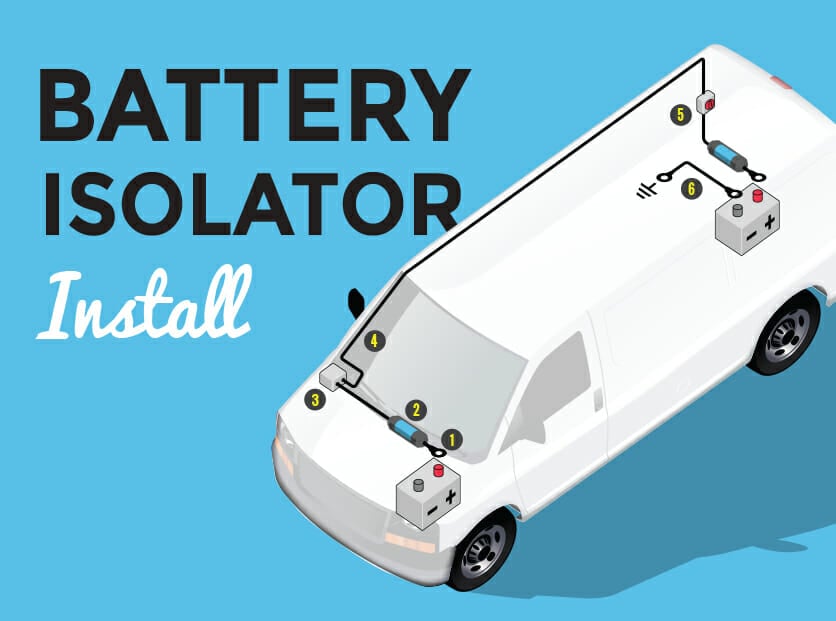
One battery is used to start the engine and the other is used to run the accessories. It shows the components of the circuit as simplified shapes as well as the power as well as signal connections between the devices. It shows the elements of the circuit as simplified forms and the power as well as signal connections between the devices. Please choose a year from the menu at left to start your search. These directions apply to the round and the rectangular dual display single voltmeters. This hybrid device uses a solid state microprocessor to control the charging and isolation functions and uses a solid tungsten points contactor relay to control the big currents.
Start light normal start light to chassis 12v to starter relay coil to coach battery to chassis ignition to ground to isolator relay coil note. Assortment of battery isolator wiring schematic. Check for continuity across the isolator relay contacts the relay should be open. An alternative indicator lamp could be connected in parallel with the relay coil. The second battery will attach to the 2 via a circuit breaker that is rated appropriately for the battery.
Gallery of Battery Isolator Relay Wiring Diagram