1 to l and c1 2 3 slow. This might seem intimidating but it does not have to be.

Ceiling Fan Switch Compatibility Guide Ceilingfanswitch Com
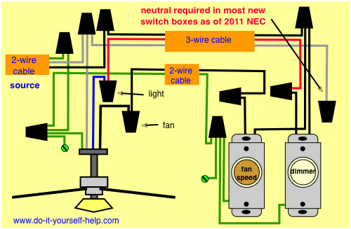
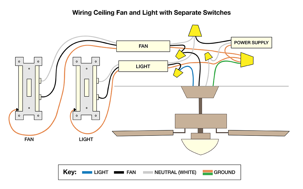
Ceiling fan direction switch wiring diagram. This wiring diagram illustrates the connections for a ceiling fan and light with two switches a speed controller for the fan and a dimmer for the lights. With this kind of an illustrative guide you will have the ability to troubleshoot stop and full your tasks without difficulty. Switched lines and neutral connect to a 3 wire cable that travels to the lightfan outlet box in the ceiling. Otherwise the arrangement will not work as it should be. Speed switch connection table. With these diagrams below it will take the guess work out.
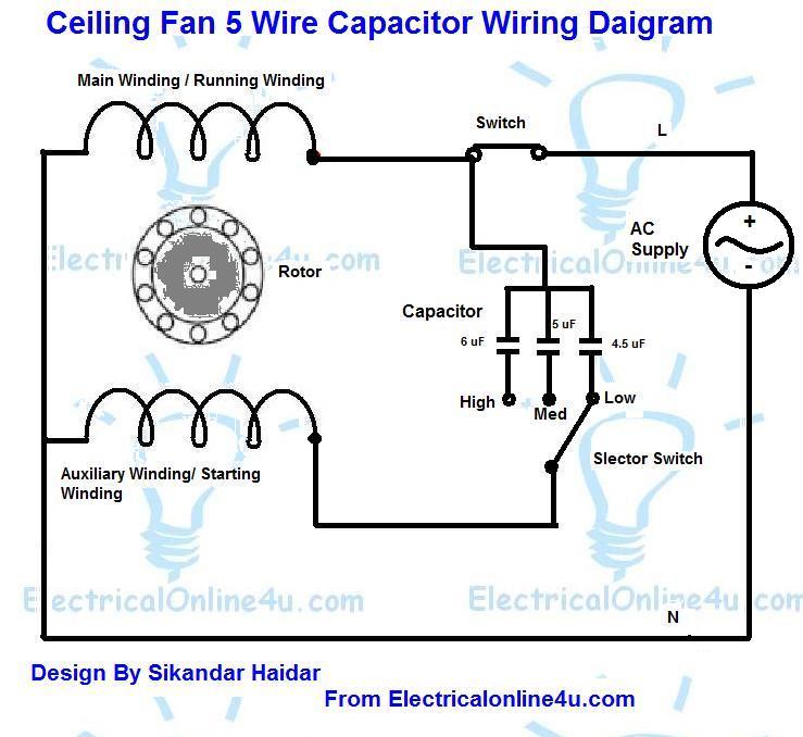
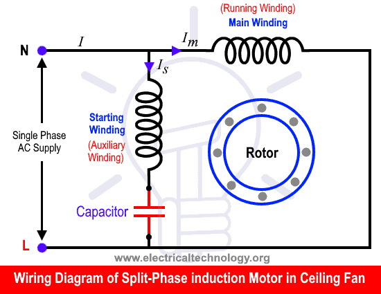
Pick the diagram that is most like the scenario you are in and see if you can wire up your fan. Each part ought to be set and connected with different parts in specific way. Ceiling fan internal wiring diagram ceiling fan internal wiring diagram ceiling fan internal wiring diagram pdf ceiling fan internal wiring schematic every electrical structure consists of various distinct pieces. Ceiling fan wiring diagram 2. 1 to l c1 1 and c1 2. 1 to l and c1 1 2 med.
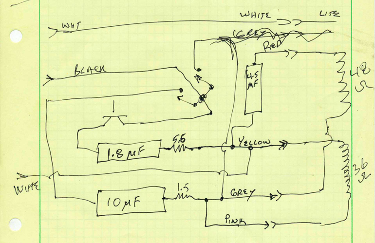
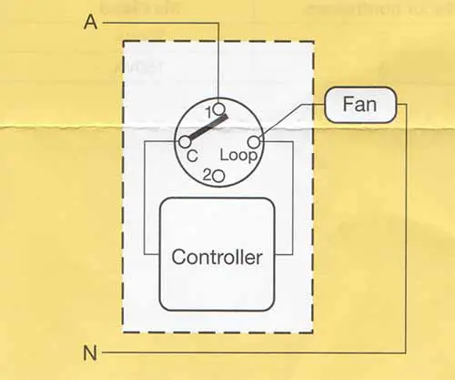
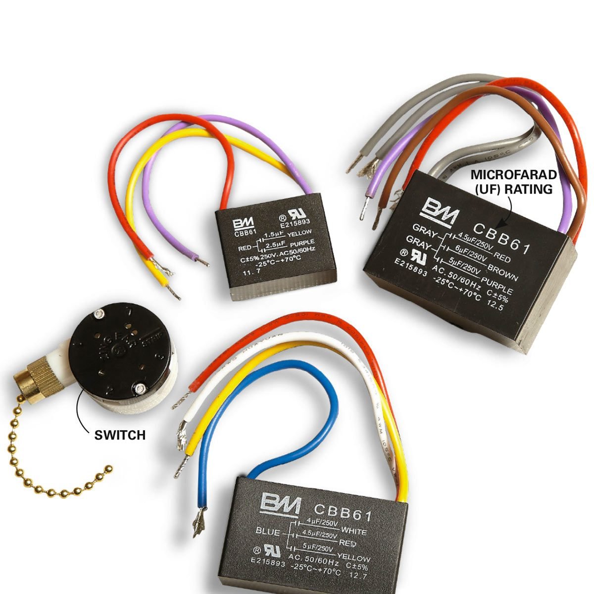
From the switches 3 wire cable runs to the ceiling outlet box. Ceiling fan wiring diagram 1. Speed switch connection table. Ceiling fan switch wiring diagram 2 line voltage enters the switch outlet box and the line wire connects to each switch. Black speed switch with only three terminals connected two wire capacitor. Take a closer look at a ceiling fan wiring diagram.
Wiring a light switch. The source is at the switches and the input of each is spliced to the black source wire with a wire nut. The fan control switch usually connects to the black wire and the light kit switch to the red wire of the 3 way cable. Hampton bay 3 speed ceiling fan switch wiring diagram youll need a comprehensive expert and easy to comprehend wiring diagram. Black speed switch three wire capacitor.
Gallery of Ceiling Fan Direction Switch Wiring Diagram