Variable potentiometer 10kω. Circuit diagram of electronic circuit breaker.

Symbols Cute Electrical Symbols Diagram Schematic Chart
Circuit breaker diagram schematic. Examples of typical elementary diagrams are shown in figures 4 5 6 7 and 8. A schematic diagram is a drawing that shows electrical system circuitry with symbols that depict electrical devices and lines representing conductors. One example of a dc schematic is a circuit breaker control schematic that shows the tripping and closing of the circuit breaker whether from controls or protective devices as well as the alarms for the circuit breaker. 997 corn wet millingunited states environmental. 997 corn wet milling 9971 general1 establishments in corn wet milling are engaged primarily in producing starch syrup oil sugar and byproducts such as gluten feed and meal from wet milling of corn and sorghum. Only qualified persons should review schematic diagrams and perform work on circuit breakers.
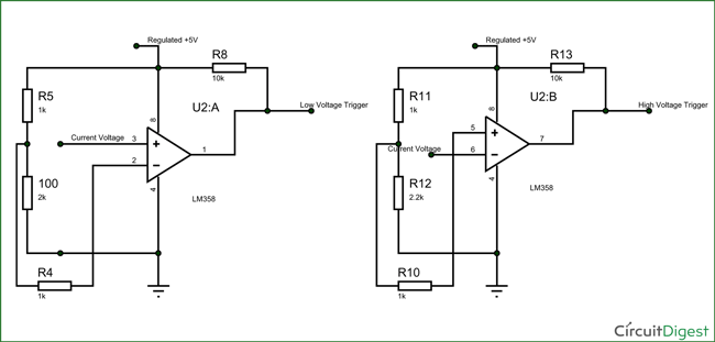
Learn to read electrical and electronic circuit diagrams or schematics. The lm358 ic is an op amp ic. Automatic bathroom light switch circuit diagram and operation. The breakers are installed in a panel so that contact is made with one of two hot bus bars running down the middle of the box. The complete schematic diagram of electronic circuit breaker is given in the image below. Bc547 ics 2 nos.
The diagram below shows a typical electromagnet design. Read further for the explanation of the same. Circuit breaker panel box wiring diagram this diagram illustrates some of the most common circuits found in a typical 200 amp circuit breaker service panel box. Wiring diagram book a1 15 b1 b2 16 18 b3 a2 b1 b3 15 supply voltage 16 18 l m h 2 levels b2 l1 f u 1 460 v f u 2 l2 l3 gnd h1 h3 h2 h4 f u 3 x1a f u 4 f u 5 x2a r power on optional x1 x2115 v 230 v h1 h3 h2 h4 optional connection electrostatically shielded transformer f u 6 off on m l1 l2 1 2 stop ol m start 3 start start fiber optic transceiver class 9005 type ft fiber optic push button selector switch limit switch etc. The hot wire in the circuit connects to the two ends of the switch. Fiber optic cable electrical connections boundary seal to be in.
But what actually happens behind all these. It is a low power. The one line diagram is similar to a block diagram except that electrical elements such as switches circuit breakers transformers and capacitors are shown by standardized schematic symbols. A schematic diagram of the circuit is given below. A one line diagram or single line diagram is a simplified notation for representing an electrical system. Step down transformer 12v.
As shown above in circuit breaker schematic it is really simple and just a bunch of resistors capacitors and other stuff. Components required for electronic cb. Resistors 1kω 2kω 22kω 51kω 10kω. How the values of the components are selected and what is the role of them here. A drawing of an electrical or electronic circuit is known as a circuit diagram but can also be called a schematic diagram or just schematic. When the switch is flipped to the on position electricity can flow from the bottom terminal through the.
7805 regulator 5v. I have tried to answer this question by breaking them into each segments and explaining. Capacitors 01μf 10μf 100μf. The basic circuit breaker consists of a simple switch connected to either a bimetallic strip or an electromagnet. In this diagram the source for the circuit is at the light fixture and the two switches come after. The hot source wire is spliced at the light box to the white cable wire running to the first switch box.
Two wire cable runs from the light to sw1 and 3 wire cable runs between sw1 and sw2.
Gallery of Circuit Breaker Diagram Schematic