Three wire cable runs between the switches and 2 wire cable runs to the light. Right now one switch operates as intended.
Installing Wall Switch Single Pole Customer Support
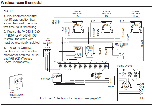
Cooper 3 way light switch wiring diagram. This 3 way light switch wiring diagram shows how to do the light switch wiring and the light when the power is coming to the light fixture. Wiring of 3 way light switches is certainly more complicated than that of the more common single pole switch so follow our 3 way switch wiring diagram. A switch provides a mechanical method for opening and closing a circuit. They are typically connected using 143 gauge electrical wire. This is the first of several related pages explaining how to control lights with multiple switches. Red and blue wires link traveler terminals of both switches.
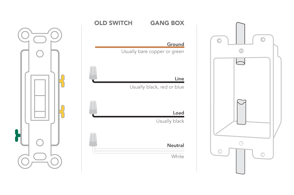
This provides three connections to complete the circuit. The black hot wire connects to the far right switchs common terminal. This might seem intimidating but it does not have to be. The black wire delivers the electricity from the panel the white wire provides the path back and the green or bare wire is the backup. For single pole applications wire the sensor switch according to wiring diagram 1 using the wire nuts provided. 3 way switch wiring diagram.
Each box has a 12 2 and 12 3 wire. Image of new 3 way switch with pilot light diagram. In this diagram power enters the fixture box. I figured itd be a easy job i hooked the wires up just as they were on the old switches. How 3 way and 4 way switch circuits work controlling a light with two or more switches this page describes how to use 3 way and 4 way switches to control lights from two or more locations. They way it was wired is the pilot lights would turn on turn the lights were on.
It shows the components of the circuit as simplified shapes and the faculty and signal associates with the devices. A light or lights can be controlled by more than one switch. Wiring diagram 3 way switch with light at the end in this diagram the electrical source is at the first switch and the light is located at the end of the circuit. Unfortunately things dont quite operate as they did. The usual practice in home construction is to use 3 way switches. Pick the diagram that is most like the scenario you are in and see if you can wire your switch.
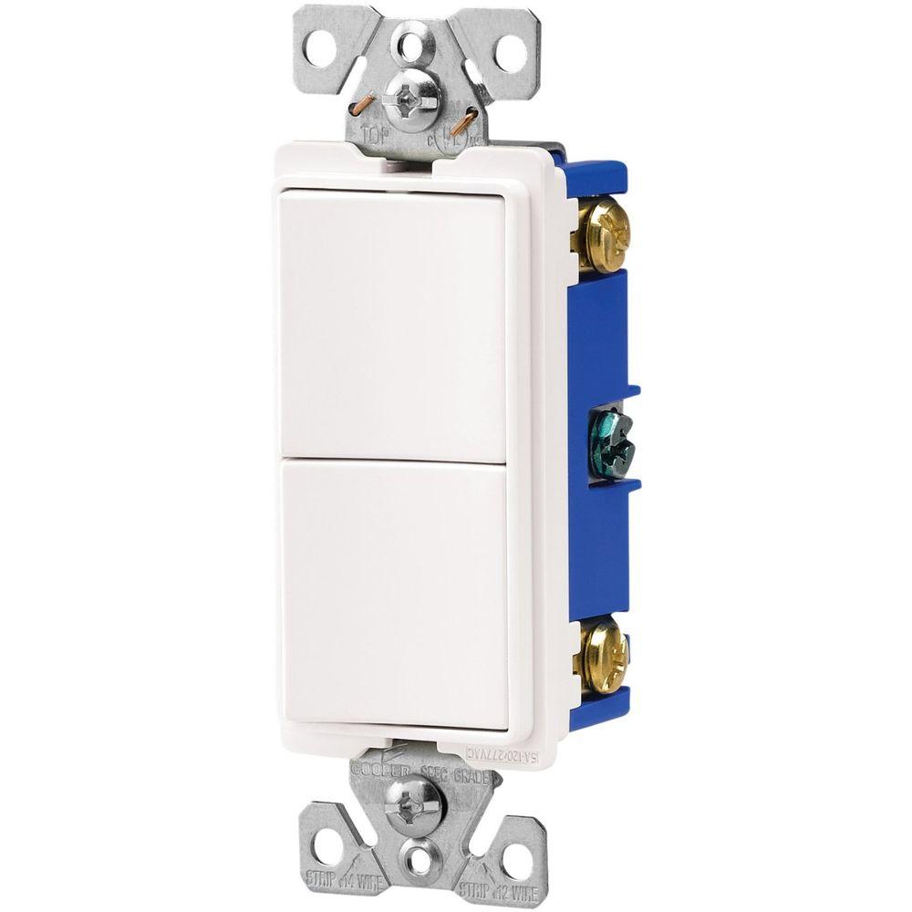
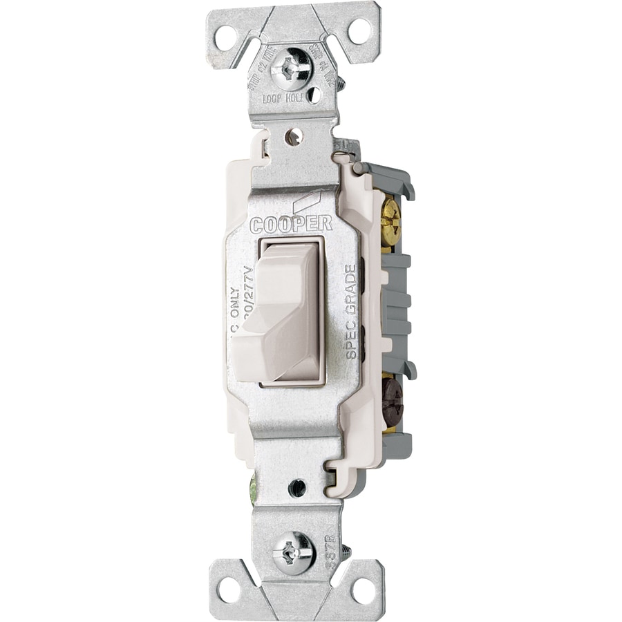
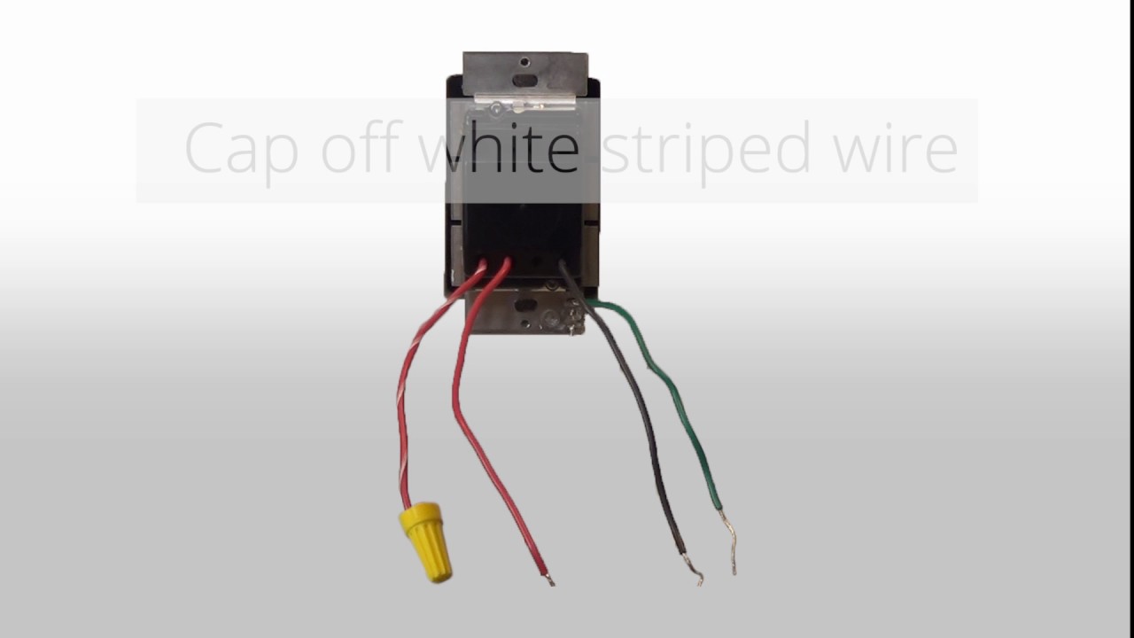
With these diagrams below it will take the guess work out of wiring. 3 way switch wiring diagram. Wiring 3 way switches with pilot light. The other switch operates the lights as intended but the pilot is always on. The 15 amp 120 volt cooper light switch 1301 7w is the standard style of switch used in modern construction. The sensor blue wire is not used and should be capped off with a wire.
Wiring is done in the same method as any other switch. Inspiring 3 way switch with pilot light diagram. Cooper 3 way switch wiring diagram wiring diagram is a simplified agreeable pictorial representation of an electrical circuit. Im replacing 2 3 way switches cooper 294 with direct replacements. The sensor red wire will connect to the wire which goes to the light fixture. Take a closer look at a 3 way switch wiring diagram.
Click here for an overview of all these pages. The sensor black wire will connect to the hot wire black in the wall box. Way light switch wiring diagram cooper multiple lights with dimmer 3 cooper dimmer switch dimmer switch outlet combo outlet wiring pass seymour 3 switch wiring diagram top how to wire 3 light cooper 3 dimmer switch wiring diagram practical wiring diagram 13 simple how to wire a three switch with 14 2 images tone tastic eaton 3 way switch diagram jaami cooper light switch wiring diagram simplified shapes 2 lights 2 7 fresh cooper light switch wiring diagram pictures simple wiring install.
Gallery of Cooper 3 Way Light Switch Wiring Diagram