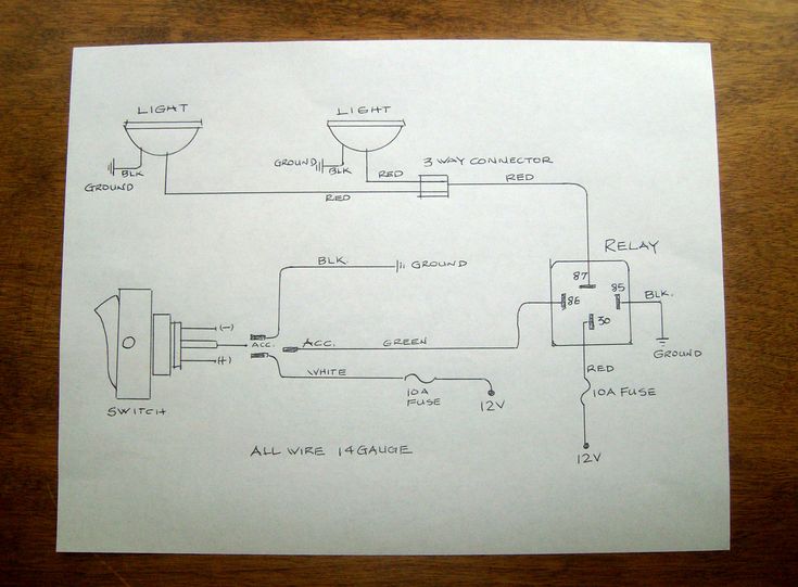
Our heavy duty and hazardous area switches provide safety reliability and long term durability in industrial environments. Wiring diagram fender telecaster 3 way switch new new 5 way switch.

Wiring Diagram 3 Way Smart Switch Wiring Diagram
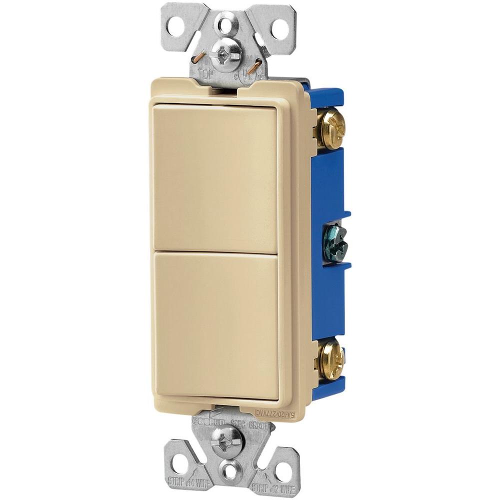
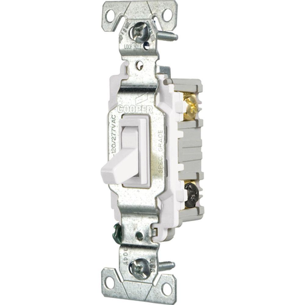
Cooper 3 way switch wiring diagram. The ground wire is pigtailed with a wire connector at the switch boxes and the ceiling box. 3 way switch wiring diagram 4 wires. Collection of fender telecaster 3 way switch wiring diagram download. All switches are engineered for smooth action and years of safe dependable service no matter what the application. Returned prepaid to cooper wiring devices quality control department at cooper circle peachtree city switch cooper wiring devices installation. Cooper 3 way switch wiring diagram wiring diagram is a simplified agreeable pictorial representation of an electrical circuit.
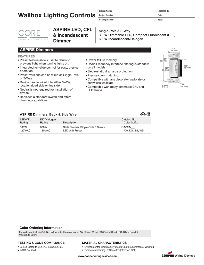
The sensor blue wire will connect to the red traveler wire in the wall. Parts list and service manual. Im replacing 2 3 way switches cooper with direct replacements. A wiring diagram typically offers info concerning the. Wiring method back side wire. Eatons full line of decorator and standard toggle switches are perfect for residential and commercial applications.
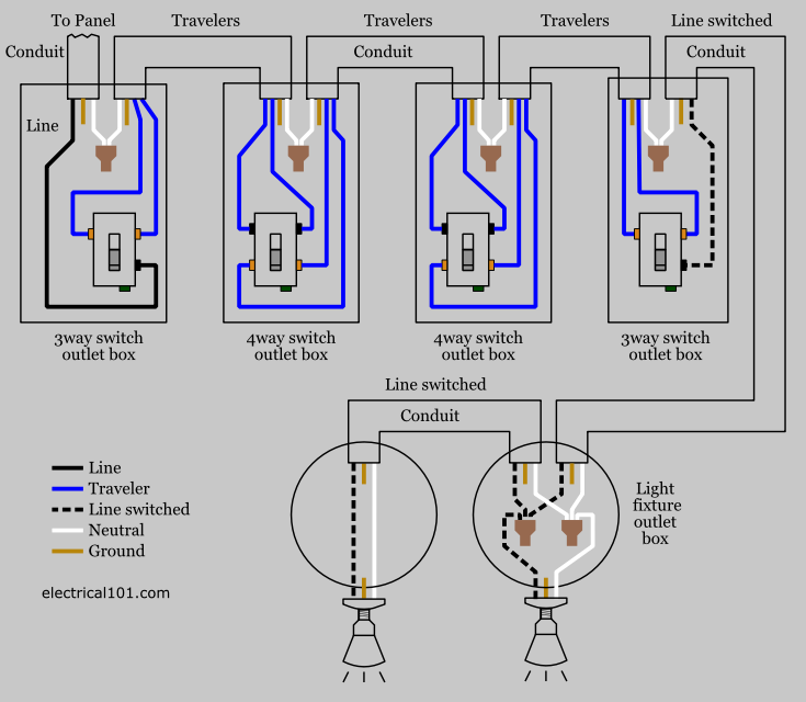
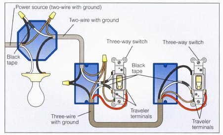
Two wire cable runs from the light to sw1 and 3 wire cable runs between sw1 and sw2. For 3 way applications wire the sensor switch according to wiring diagram 2a or 2b using the wire nuts provided. This might seem intimidating but it does not have to be. 3 way switch wiring with. Three way switch wiring with light middle. Pick the diagram that is most like the scenario you are in and see if you can wire your switch.
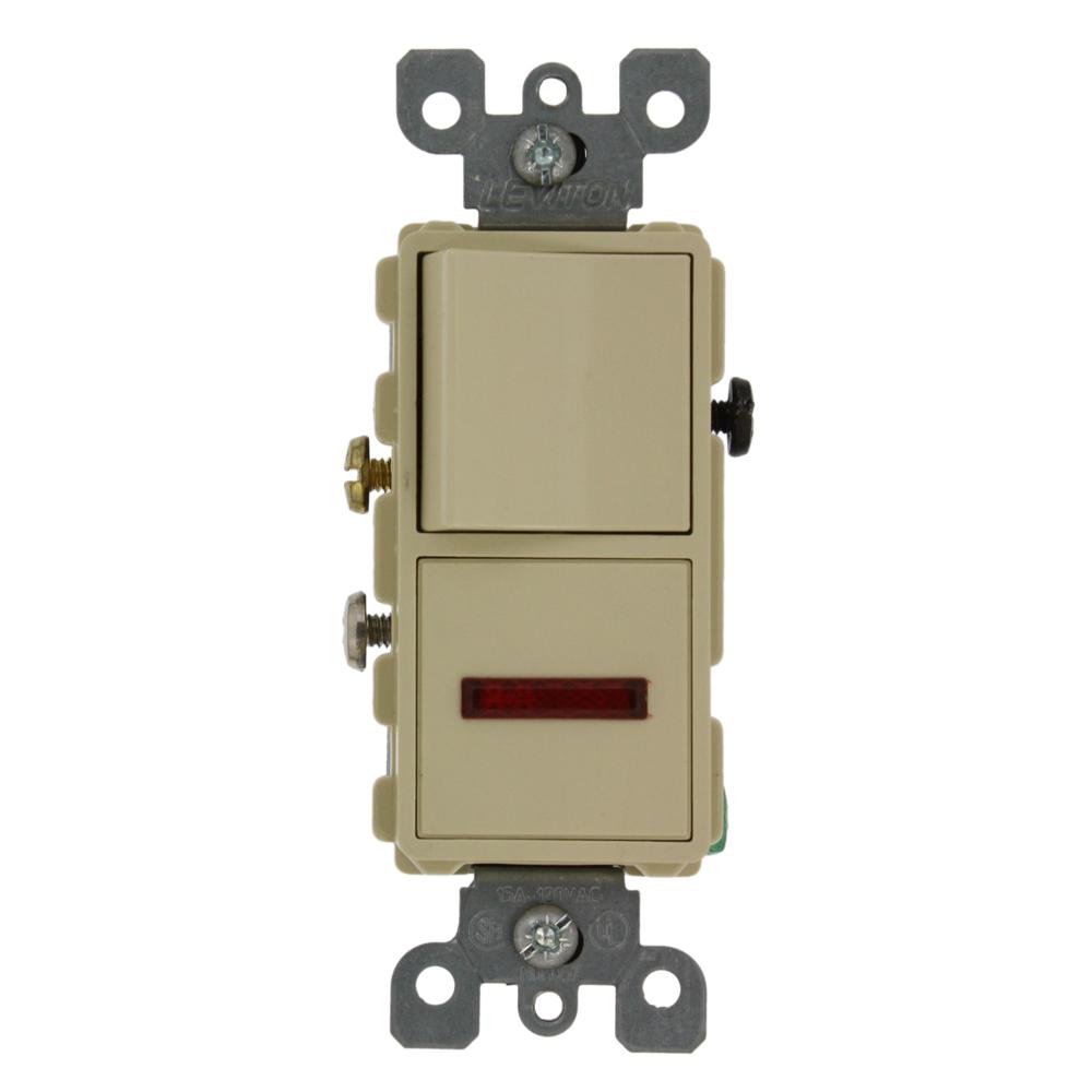
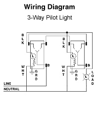
Take a closer look at a 3 way switch wiring diagram. I figured itd be a they way it was wired is the pilot lights would turn on turn the lights were on. It shows the components of the circuit as simplified shapes and the faculty and signal associates with the devices. It shows the elements of the circuit as streamlined shapes and the power and also signal links in between the devices. Combination slot phillips head mounting catalog number configuration single pole switch pilot light 3 way switch pilot light. The source in this circuit is at the first switch and the light fixture is.
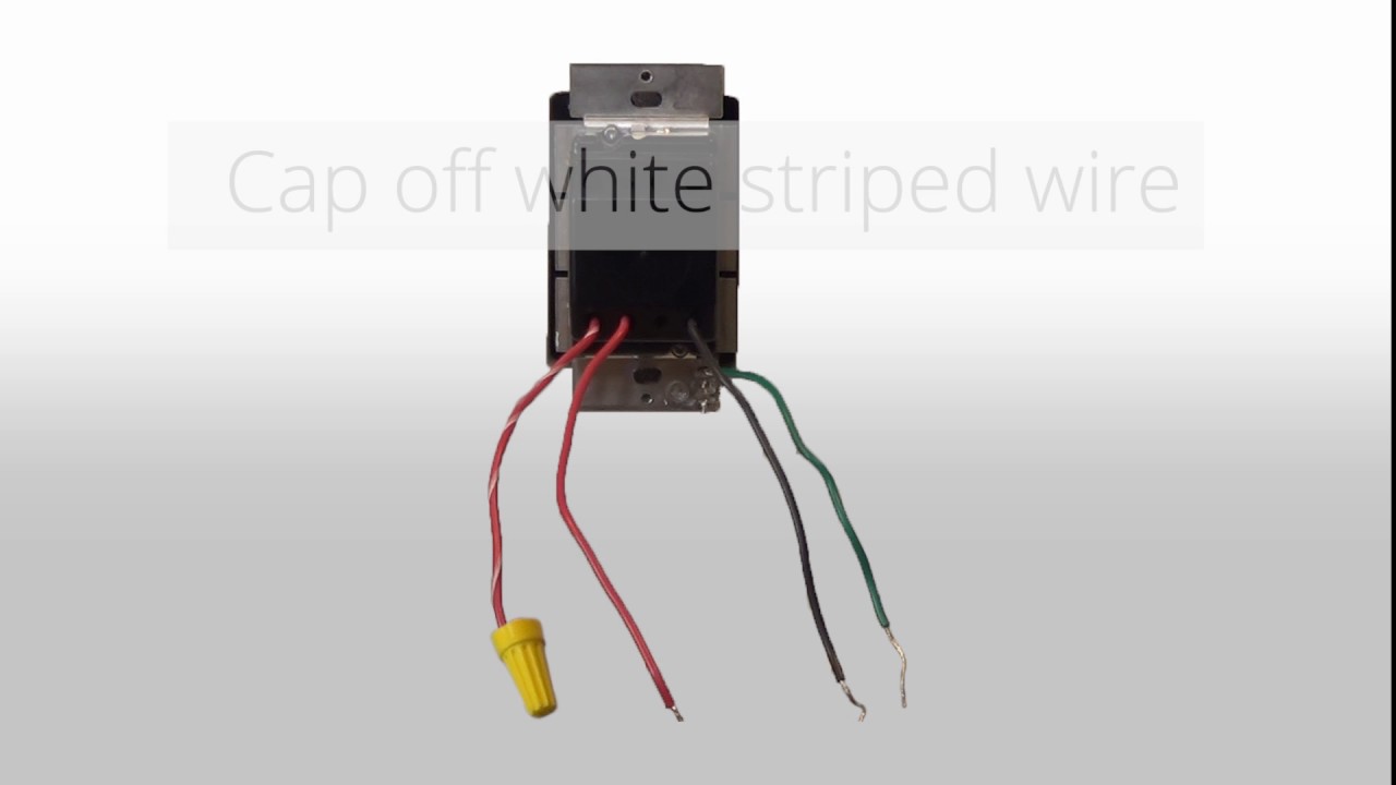
Motion sensing 3 way wall switch 2 pages the motion sensing wall switch dectects motion to turn on connect the detector as shown in the diagram. 3 way switch wiring diagram. In this diagram the electrical source is at the first switch and the. Wiring diagram for reference. Assortment of fender telecaster 3 way switch wiring diagram. A wiring diagram is a simplified conventional photographic depiction of an electric circuit.
The sensor may be placed at either end of the 3 way circuit. The sensor black wire will connect to either one of the black wires in the wall box. 3 way switch wiring diagrams wiring diagram 3 way switch with light at the end. With these diagrams below it will take the guess work out of wiring. Cooper wiring diagram single pole light switch explained bination double leviton three way dimmer switch wiring diagram fresh cooper 3 for with wiring diagram cooper 3 way switch refrence. The sensor red wire will connect to the other black wire in the wall box.
Remove the existing switch in the location where the sensor will be installed. With these diagrams below it will take the guess work out of wiring.
Gallery of Cooper 3 Way Switch Wiring Diagram