Terminal 1 line 2 120volt power terminal 2 t4 terminal 3 t5 terminal 4 t8 terminal 5 t2 and t3 terminal 6 no connection you need a safety switch in line of the 240 volt to turn all power off for maintenance or any work on the machinethe drum switch will stop the motor in the off position but all power is not removed. Wire your drum switch as below.

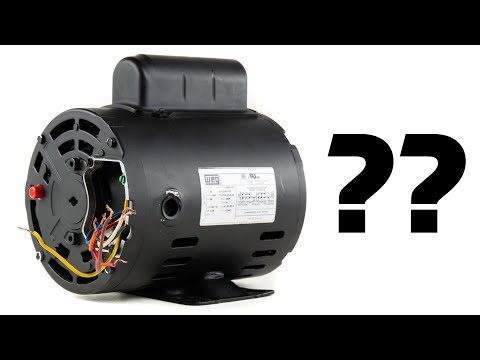
Dayton 115 Volt 2 Speed Motor Wiring Youtube
Dayton motor wiring color code. The one you have will work fine they are used often at motor. Easy online ordering for the ones who get it done along with 247 customer service free technical support more. 4z 15 i replace this electric motor and it has 4 lugs i have 3 wires blk red and white. Motor service factor. Dayton electric motors wiring diagram hvac condenser wiring diagram new wiring diagram dayton ac electric motor refrence wiring diagram. Dayton electric motors wiring diagram wiring diagram dayton ac electric motor refrence wiring diagram motor fan fresh pretty 3 wire condenser fan motor.
I dont see a 5 terminal 6 brown. Line 1 straight 120 volts to t1 drum switch. 9z 12 volts dc 18 hp amps. There is a sticker on wiring diagram ideally color for dayton. Click on the image to enlarge. For the drum switch you would need the motor wires red black and orange with the black and red wires being the wires for forward and reverse.
All wiring should be in accordance with national electrical code or other local codes. Graingers got your back. 1 line in 2 brown 3 white red orange 4 yellow and line in 5. Dayton model 6k759 34 hp 115230v 1 phase 1725 rpm capacitor start ac motor furnas rsb5 reversing controller drum switch. For 120 volt it would be from the power cordblack l1 white l2. Painted and stainless steel for both fresh and saltwater lifts from 34 hp through hp.
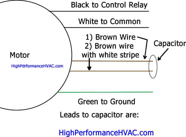
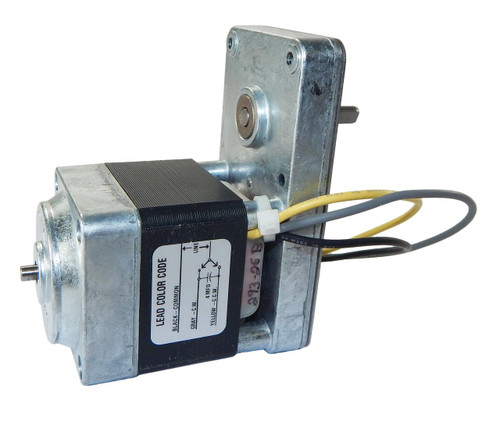
9z 12 volts dc 18 hp amps. Diagram dd6 diagram dd7 m 1 ln e diagram dd8 ln e l1 l2 l3 sc z1 u2 z2 u1 cap. Wiring diagram sheets detail. And upwards diagram dd5 two speed motors for all other single phase wiring diagrams refer to the manufacturers data on the motor. Thermal contacts tb white m 1 z2 yellow z1 blue u2 black u1 red bridge l1 and l2 if speed. Motor has the following wiring color configuration on the terminals.
A flat plate hoist using an electric motor to drive a worm reduction is one of the most. All wiring should be in accordance with national electrical code or other local codes. 08 16 2014 1227 pm 3. Motors and wiring diagrams for power unit machines. Looking for dayton 14 hp general purpose motorcapacitor start1725 nameplate rpmvoltage 115208 230frame 56 5k263. Wiring diagrams motors to switch.
4z 15 looking for dayton 34 hp instant reverse motor nameplate rpm voltage motor thermal protection manual. Collection of dayton electric motors wiring diagram.
Gallery of Dayton Motor Wiring Color Code