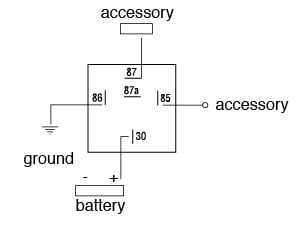
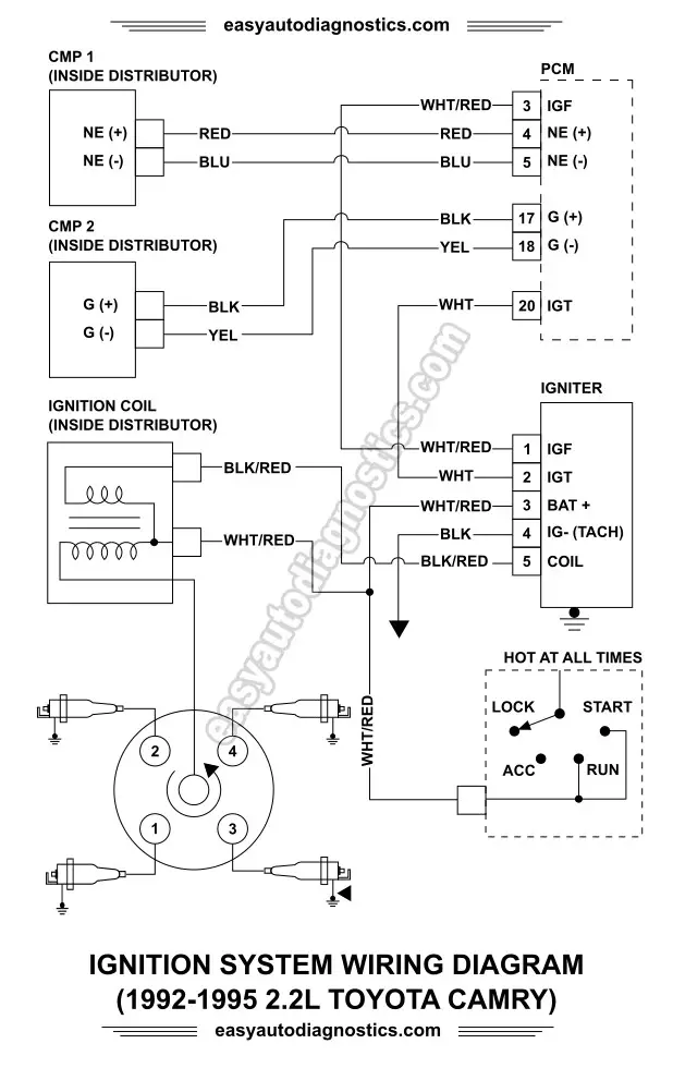
3 4 1 2 rectange so which wire goes where. I will have a basic spst switch to trip the relay i have a denso 4 pole relay used for fuel pump window motors etc and i would just like to know which poles go to what.

Denso Oxygen Sensor Wiring Diagram Bmwiok Alpa Zografisch Nl
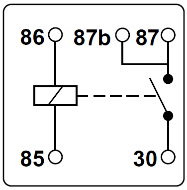
Denso 5 pin relay diagram. I cover 34 and 5 pin relays and all you need is a 12v source a multimeter and a test light. When the 5 pin relay is de energized off pins 4 and 5 have continuity. Ii single pole double throw spst such relay has 5 terminal pins which consists of a pair of coil pins a common pin a normally open no pin and a normally closed nc pin. Electric fan relay wiring diagram wiring block diagram 5 pin relay wiring diagram. Lost my diagram manual and need to wire up a relay for my blower motor. Both 4 and 5 pin designs are used in both standard mini and micro sizes.
3 pin 4 pin 5 pin iso standardized relays iso relays were designed to try and standardize relay connections making it easier to test and design systems. When a relay contact is closed there is a closed contact when the relay is not energized. When the relay is energized on pins 3 and 5 have continuity. Iso is short for international standard. The book includes a large amount of sensible tips for different circumstances that you may experience if youre dealing with wiring problems. Here is a video on how you can test a relay with or without a diagram.
Relays are the integral component of any car wiring. No car wiring can be complete without these. Also when the relay is deactivated from activated state the common pin will conversely break away. Registered users of the site do not see these ads. Relays are generally used to switch smaller currents in a control circuit and do not. Iso relays are currently used by almost all automotive manufacturers today.
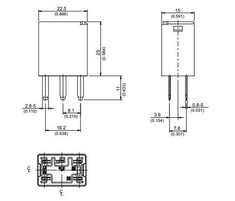
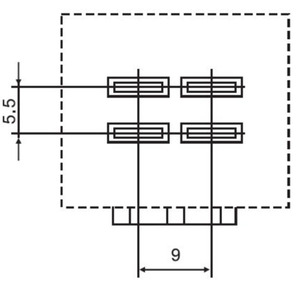
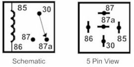
The diagram on the relay is as follows. Denso relay 4 pin wiring diagram. Multimeter used in video. Here we look at relay switch pin diagram and the different kinds of relay switches. Here is a picture gallery about 5 pin bosch relay wiring diagram complete with the description of the image please find the image you need. Relays are used to bypass signal wire and directly supply current from battery thus your car wiring remains safe from heating up and burning due to the load of heavy components.
Wiring diagram includes numerous comprehensive illustrations that show the relationship of varied things. When the relay is not activated the common pin is in contact with the nc pin and when it is activated the common pin will break away from contact with the nc pin and subsequently makes contact with the no pin. Tridon guarantee the tridon products listed in this catalogue are guaranteed to be free of defects in materials and workmanship for the following periods. Relays switches are used to open and close circuits electromechanically or electronically. Relay pin identification guide 39 terminal codes for tridon relays 39 type of relay contacts 39 general relay range 40 cross reference guide 44. It contains directions and diagrams for different varieties of wiring strategies and other things like lights windows and so on.
Each and every one of. Bosch 5 pin relay spotlight wiring diagram bosch 4 pin relay inside 5 pin bosch relay wiring diagram image size 800 x 645 px image source. When a relay contact is open the relay is not energized. Sponsored links registered users of the site do. Electronic and electro mechanical flashers 2 years thermal flashers 1 year general relays 1 year this warranty does not apply to. In either case applying electrical current to the contacts will change their state.
Flashers or relays that have been modified or altered in any way. Denso parts are often used in japanese assembled cars including cars manufactured by renowned brands like toyota honda mitsubishi suzuki mazda daihatsu and several others.
Gallery of Denso 5 Pin Relay Diagram