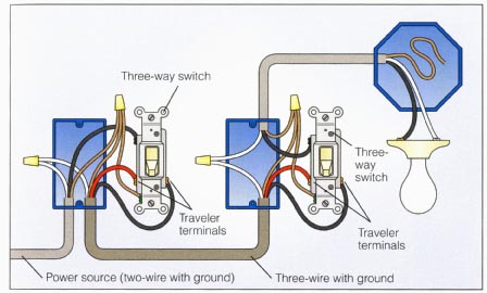
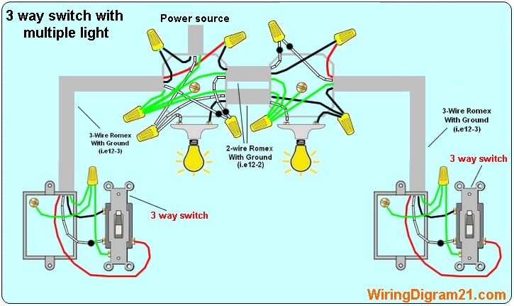
The pair of travelers on one switch connect to the pair of travelers on the other switch. Controlling more than one light.

Power Switch Light 3 Way Fan 1 Fan Light Switched Separately
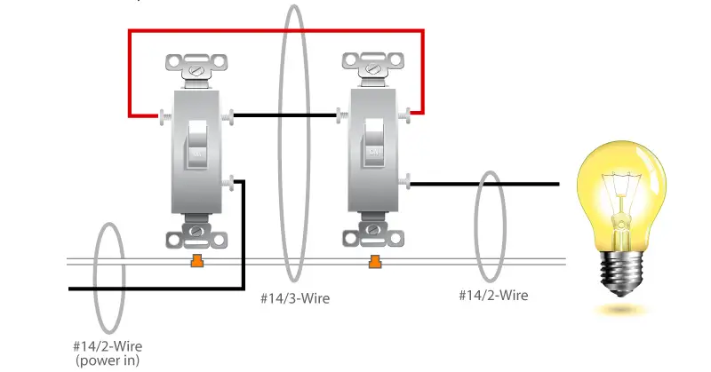
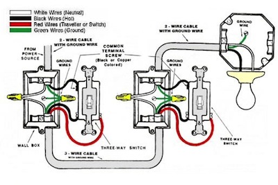
Different 3 way switch wiring. Pick the diagram that is most like the scenario you are in and see if you can wire your switch. Below is a variation with the light between the two switches ie panel switch light switch. Each 3 way switch in these examples are controlling the power source to the same load. 3 way switch wiring diagram. With conventional wiring the common wire from one switch connects to line the common wire from the other switch connects to the load lights. There are three screw terminals on the body of the switch in addition to the green grounding.
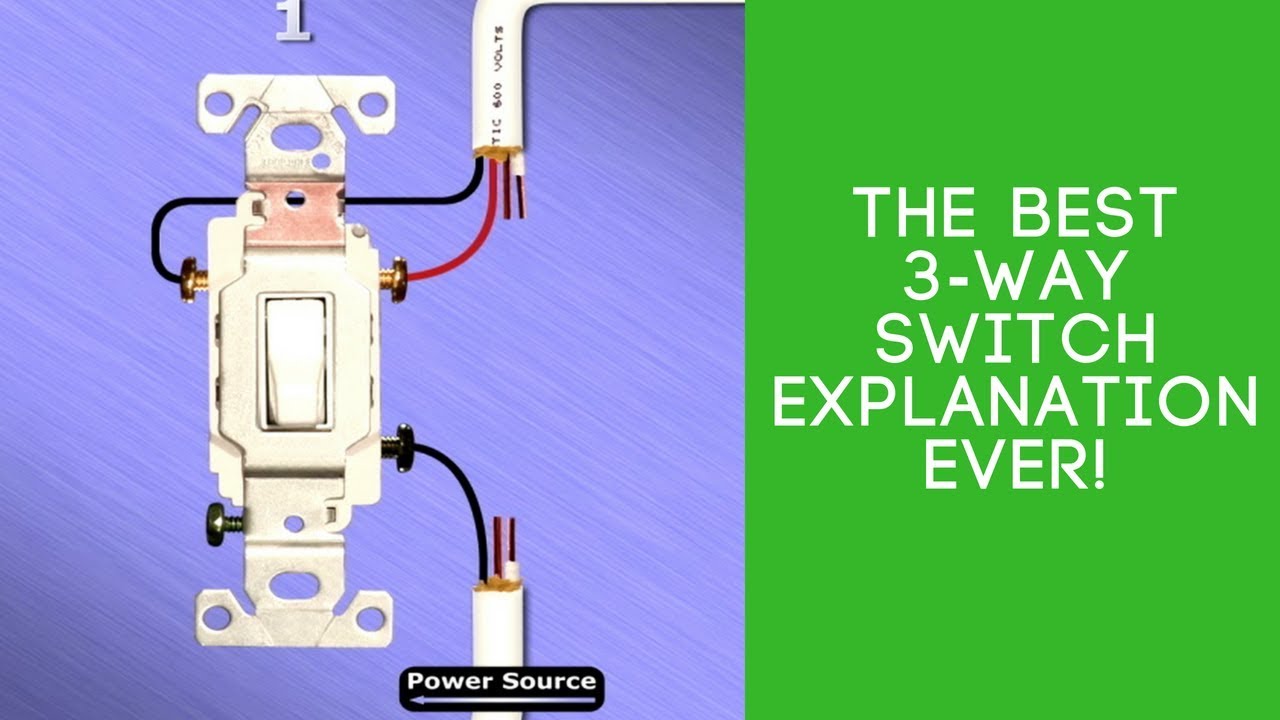
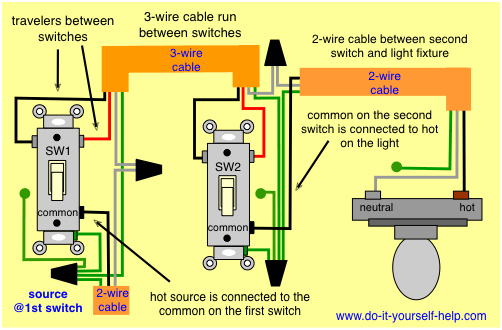
The black and red wires between sw1 and sw2 are connected to the traveler terminals. With these diagrams below it will take the guess work out of wiring. Then a 4 wire cable going between the two 3 way switches and then a 3 wire cable going from the switches to the load. All three way switch and 2 way switch wiring diagrams have the same basic components. 3 way switches have three terminals one common usually black color and one pair of travelers usually brass color. Traveler wires are interchangeable on each switch.
Any of the above can be modified to control multiple lights. Additional lights are just. Take a closer look at a 3 way switch wiring diagram. A third type is the four way switch which is used in conjunction with two three way switches to control lighting from more than two locations. Such markings are not needed with this type of switch as they are. There are two clear giveaways that identify a switch as being a three way type.
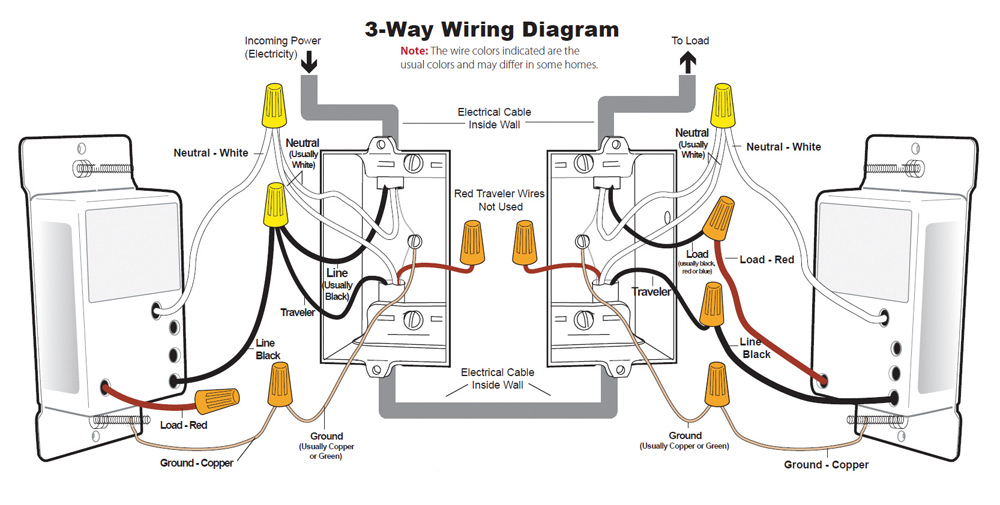
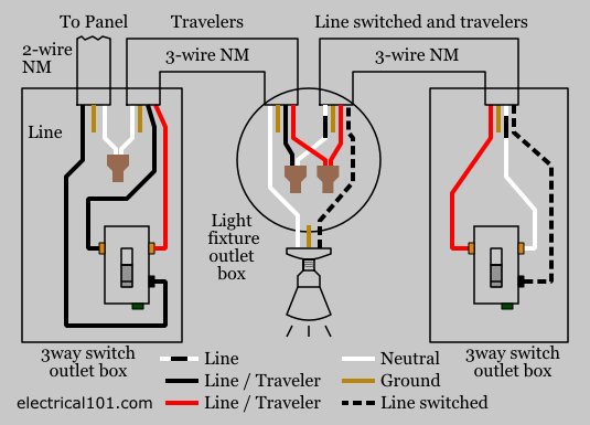
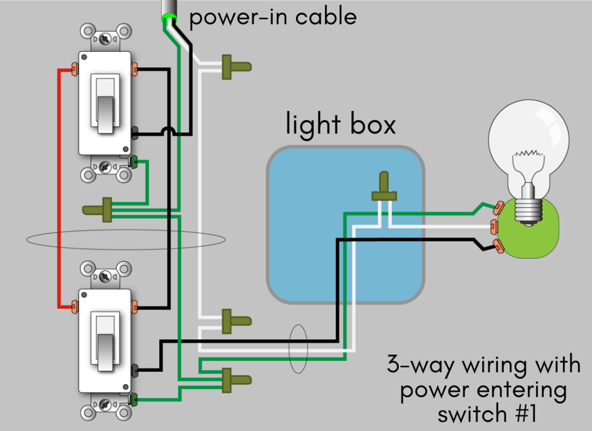
In this diagram the incoming hot wire attaches to the first switchs common dark colored terminal. Conventional 3 way switch wiring configuration. This might seem intimidating but it does not have to be. The common terminal of the second 3 way switch connects to the light fixtures. There are no onoff markings on the switch toggle. Components of 3 way switch wiring.
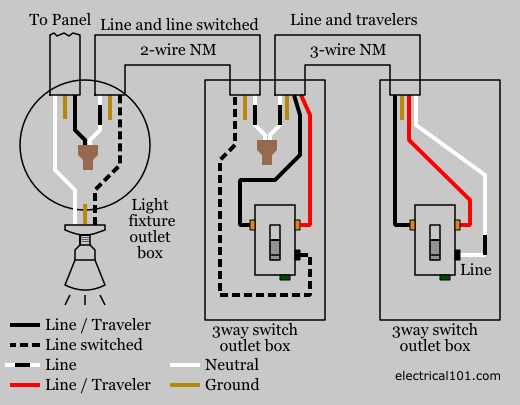
The three way switch is a variation of the standard single pole switch which controls a light only from one location. A 3 wire nm connects the traveler terminals of the first and second 3 way switch together. This 3 way switch wiring diagram shows how to wire the switches and the light when the power is coming to the light switch. The black line wire connects to the common terminal of the first 3 way switch. Three way switches are always used in pairs and include special wiring connections. 3 way switch circuits variations single light circuits.
If you are trying to troubleshoot a 3 way switch operation then you will need to identify the function of each wire. The white neutral wires are connected together in each switch box. All of the switches shown below are 3 way. When wiring a 3 way switch circuit we will be using a 3 wire cable known as romex coming from the source such as the breaker box. Three wire cable runs between the switches and 2 wire cable runs to the light. Diagrams shown on this page are simplified for clarity.
Wiring diagram 3 way switch with light at the end in this diagram the electrical source is at the first switch and the light is located at the end of the circuit. The two hot wires of three wire cable connect to a pair of brass colored traveler terminals on each switch. Wires consisting of a line a load a neutral a pair of travelers and two 3 way switches.
Gallery of Different 3 Way Switch Wiring