A drawing of an electrical or electronic circuit is known as a circuit diagram but can also be called a schematic diagram or just schematic. Selects between two connections.
Circuit Diagram
Electric circuit schematic diagram. By using this site you agree to our use of cookies. To read electrical schematics the fundamental electrical schematic symbols should be. Learn more got it. Wires are not connected. Master the analysis and design of electronic systems with circuitlabs free interactive online electronics textbook. Design with our easy to use schematic editor.
Symbol component name meaning. Circuit diagram design and share diagrams using a wide range of components. Electrical schematics are the maps for designing building and troubleshooting circuits. This site uses cookies. Posted by james freeman 05062020. Electrical diagram how tos beginners guide how to read electrical schematics.
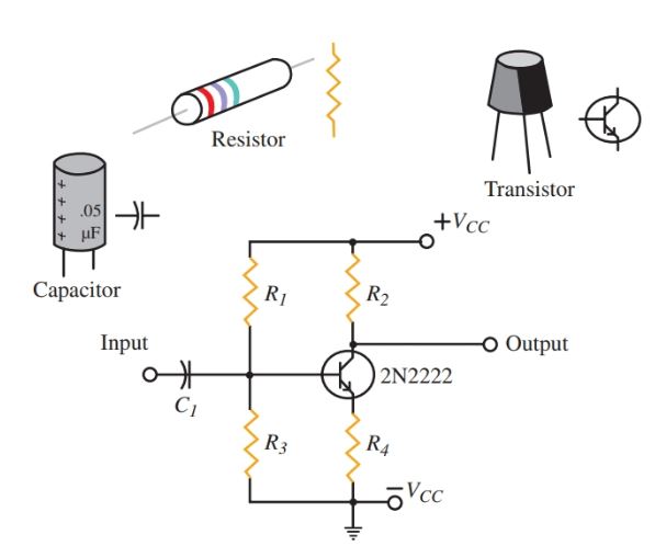
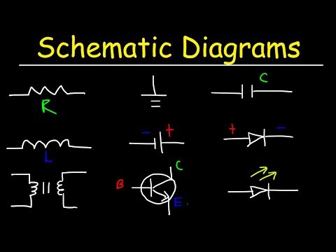
Circuit diagram is a free application for making electronic circuit diagrams and exporting them as images. Table of electrical symbols. Design circuits online in your browser or using the desktop application. Launch circuitlab or watch a quick demo video interactive electronics textbook new. Disconnects current when open. In order to learn how to read a circuit diagram it is necessary to learn what the schematic symbol of a component looks like.
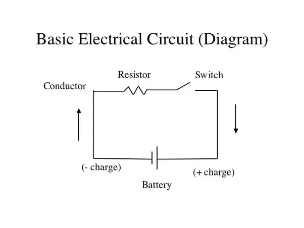
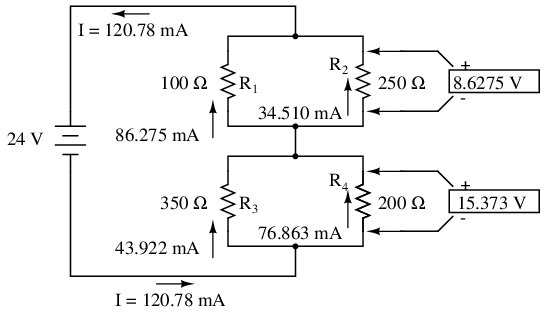
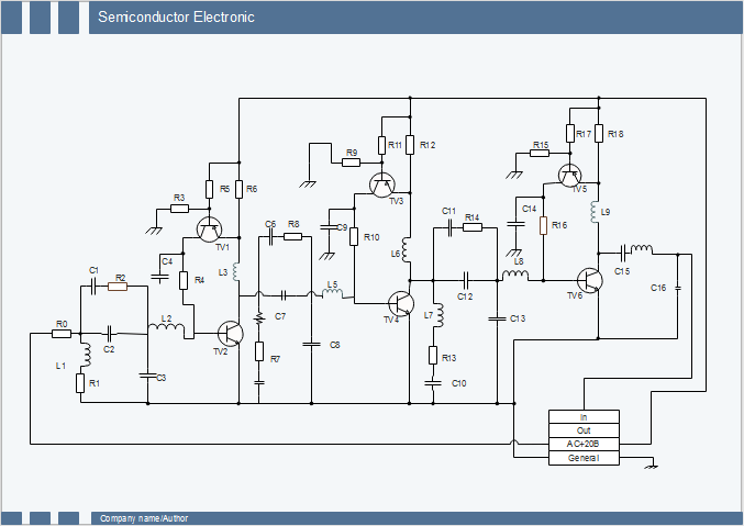
The presentation of the interconnections between circuit components in the schematic diagram does not necessarily correspond to the physical arrangements in the finished. Circuit or schematic diagrams consist of symbols representing physical components and lines representing wires or electrical conductors. Basic electrical circuits and theory branch circuit wiring a basic top view floor plan terminology block diagram. Refer to this page to learn the differences between schematic diagrams and circuit diagrams. The main function of the rectifier is to. A wiring diagram is a simple visual representation of the physical connections and physical layout of an electrical system or circuit.
This article illustrates the differences between schematic diagrams and circuit diagrams and it may benefit you a lot in identifying the components of an electric system tracing a circuit and even fixing electrical. It is also. One is the neutral wire and the other is the live wire. It shows how the electrical wires are interconnected and can also show where fixtures and components may be connected to the system. A simplified conventional graphical representation of an electrical circuit. Electrical symbols and electronic circuit symbols are used for drawing schematic diagram.
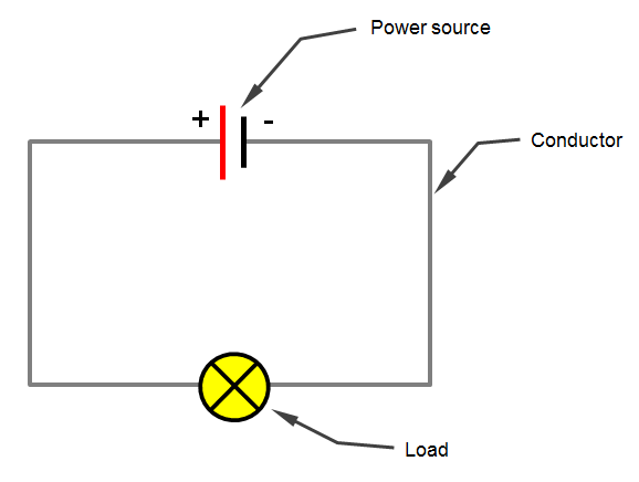
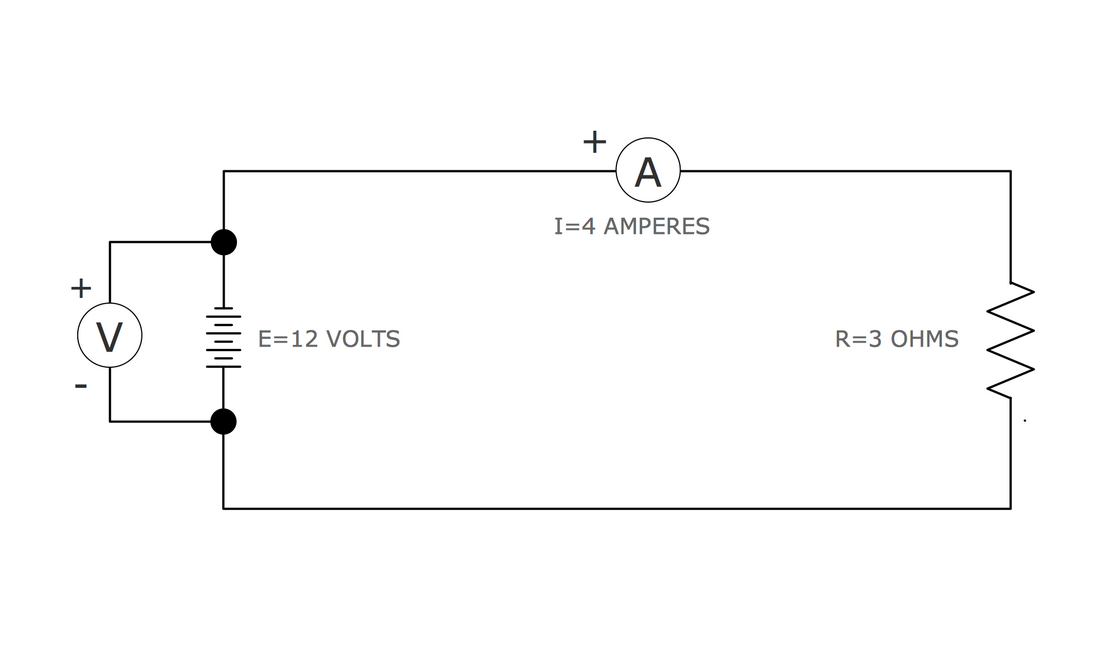
Switch symbols and relay symbols. Battery charging is done by means of a rectifier. Analog digital circuit simulations in seconds. For a lamp we need two wires. Learn to read electrical and electronic circuit diagrams or schematics. Schematics circuit diagrams wiring diagrams electrical diagrams are commonly used in engineering diagrams.
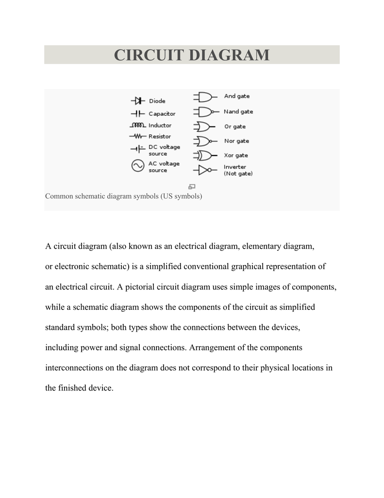
This tutorial will turn a beginner into a fully learned schematic reader. Circuit drawings and wiring diagrams electrician 2 youth explore trades skills circuit drawing diagram. A user friendly program for making electronic circuit diagrams. The symbols represent electrical and electronic components. A circuit diagram electrical diagram elementary diagram electronic schematic is a graphical representation of an electrical circuita pictorial circuit diagram uses simple images of components while a schematic diagram shows the components and interconnections of the circuit using standardized symbolic representations. Launch it instantly with one click.
Learning how to read and understand schematics will be easy for beginners with recognizing basic schematic symbols. Professional schematic pdfs wiring diagrams and plots. 10 simple electric circuits with diagrams ac circuit for lamp. Practical circuit design and analysis. You may have heard them very often but they vary each other slightly. A diagram of a system in which the principal parts or functions are represented by blocks connected by lines that show the relationships of the blocks.
Conductor of electrical current.
Gallery of Electric Circuit Schematic Diagram