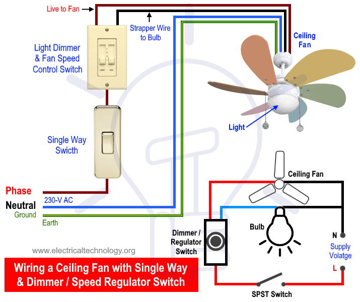
With this arrangement the switches control power to the ceiling box and a pull chain is used to control fan speed. This diagram shows the wiring arrangement for a 3 way switched outlet.

Gr 3534 Cadamp Efsc5 1ph 5 Amp Fan Speed Controller Efsc50
Fan speed controller wiring diagram. The ecm motor must use a pwm 0 10vdc or 10 0vdc control signal to be compatible with the 759 ecm controller. Collection of hunter 3 speed fan switch wiring diagram. It shows the components of the circuit as streamlined forms and also the power and also signal connections in between the devices. The source is at sw1 and 3 wire cable runs between all the devices. 4 wires come out of wall. Wiring a ceiling fan dimmer control switch electrical question.
Replacing with hunter model 27182 dimmer fan control switch. Is there a wiring diagram for the 40csfm 3 speed fan controller. Hoffman controls offers a compatible 115hp 115vac 500 1800rpm ccw 0 10vdc ecm motor pn 520 1800 759 or a pwm ecm motor pn 510 1800 759 which includes a wiring kit as shown below. Turn fan switch on and check fan speed controller operation by turning control knob through full range. Connect the 32e500f in accordance with the wiring diagrams on page 6. 3 way switched outlet wiring diagram.
The source is at the switches and the input of each is spliced to the black source wire with a wire nut. 2 black 2 white with ground both white wires are connected together leaving the black wires to be hooked up to the new switch. With this wiring the receptacle can be controlled from two locations. For more ceiling fan wiring diagrams check this link. This feature allows the fan to rapidly increase speed to the set level and thus provides. 72 kick start feature the 32e500f series fan speed controllers incorporate a kick start feature providing a short burst of power at start up to overcome the inertia of the fan.
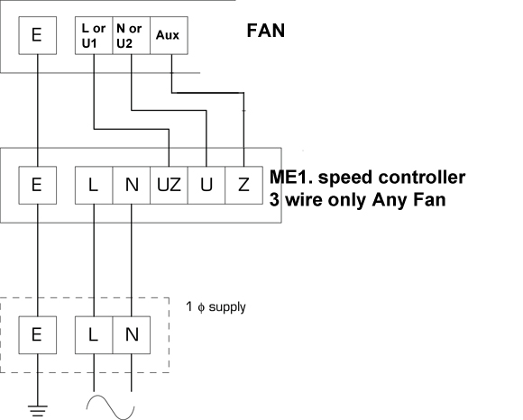
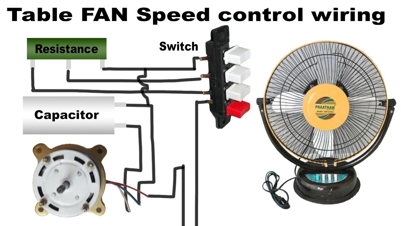
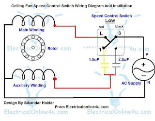
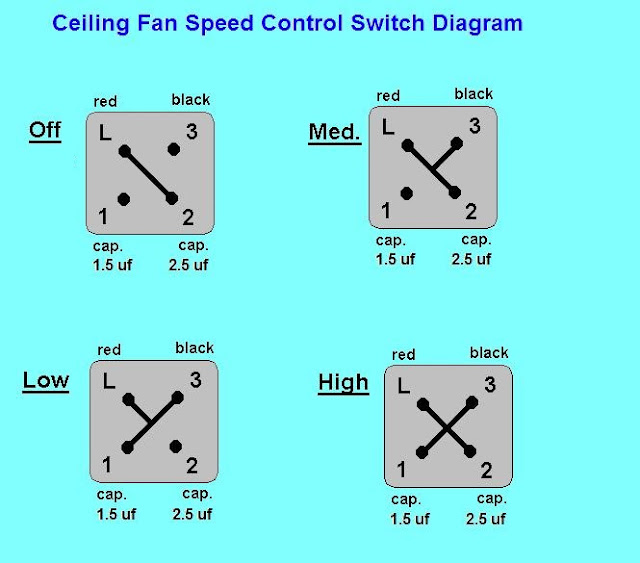
In the above ceiling fan speed control wiring diagram i shown the main winding running winding and i connect run wire of motor to the speed control switch and you can see it in above diagram that connection of run wire of motor in switch l point and and 1 and 2 for capacitor. It shows the parts of the circuit as simplified forms and the power and signal links between the gadgets. Refit switch plate to wall. A wiring diagram is a simplified traditional pictorial representation of an electrical circuit. A wiring diagram is a streamlined standard pictorial representation of an electric circuit. Bridge l1 and l2 if speed controller sc is not required m 1 ln e white brown blue l1 l2 n sc bridge l1 and l2 if speed controller sc is not required diagram dd9 1ø wiring diagrams ln e l1 l2 l3 sc z2 u2 z1 u1 cap.
Tions and wiring diagram the type of control signal the motor uses to vary the motor speed. From the switches 3 wire cable runs to the ceiling outlet box. Hunter breeze fan light switch. Thermal contacts tb white m 1 z2 yellow z1 blue u2 black u1 red bridge l1 and l2 if speed controller sc is not required anti clockwise clockwise these diagrams are current at the time of publication check the wiring diagram supplied with the motor. Collection of canarm fan speed control wiring diagram. It may be necessary to remove the fan.
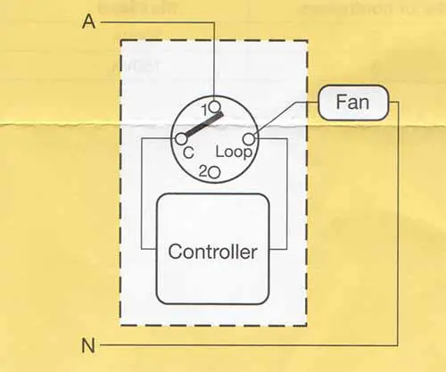
The hot wire from the source connects to the common terminal on sw1 and the. How is a dimmer and fan control switch wired for my ceiling fan. Installation cont installation cont installation tip. This wiring diagram illustrates the connections for a ceiling fan and light with two switches a speed controller for the fan and a dimmer for the lights. 06 december 2019 there is a wiring diagram available.
Gallery of Fan Speed Controller Wiring Diagram