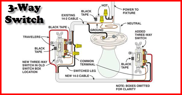
When replacing an existing 3 way switch take note of how the existing switch is wired before you remove the wiring then refer to your notes to help you wire the new 3 way dimmer switch. For more information on household ac current and grounding see how power distribution grids work you can see in the figure that the current runs through the switch.
3 Way Switch Wiring Diagram
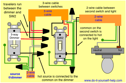
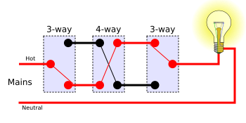
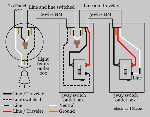
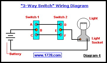
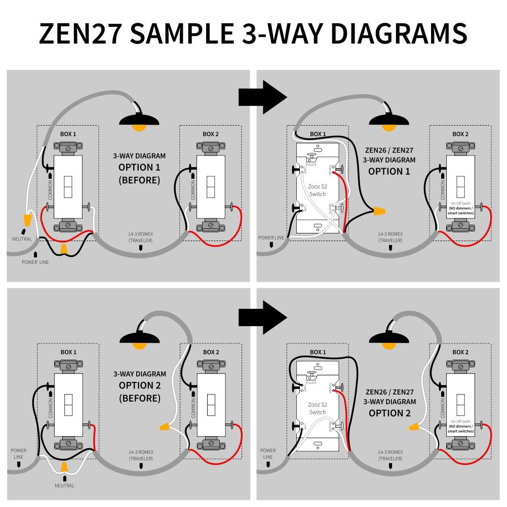
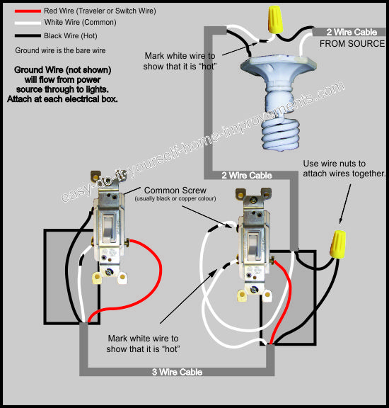
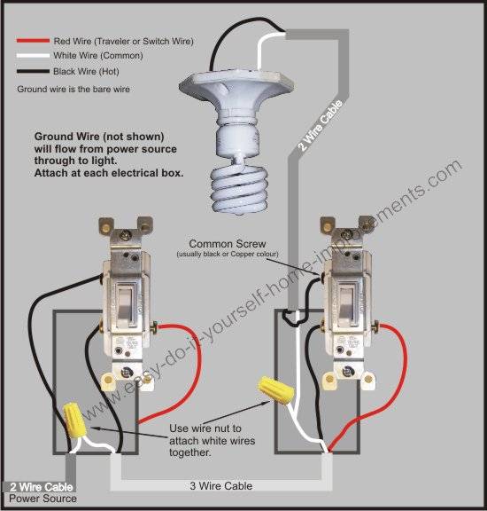
How does a 3 way switch work diagram. Pick the diagram that is most like the scenario you are in and see if you can wire your switch. The diagram below provides a simple layout of a three way light setup and you can see the red wire is the extra wire thats needed to make it all happen conveniently enough red wire is normally used in real life in three way circuits as well. If you are replacing an existing 3 way switch. Many manufacturers are now producing dimmer switches that can be used for either single pole or 3 way switches. This 3 way switch wiring diagram shows how to wire the switches and the light when the power is coming to the light switch. For example they can be arranged so that the feed cable runs to the first three way switch then to the light fixture box then to the second three way switch.
How it works is that the hot wire coming in from the electrical panel is connected to the common screw of the first light switch in the circuit. In this diagram the incoming hot wire attaches to the first switchs common dark colored terminal. Three way switches can be wired in a number of different ways depending on where they are located relative to the light fixture in the circuit cable runs. The photo shows a dimmer switch that can be used as a single pole switch or as a three way switch. In this article we will solve the mystery of three way switches. Single engine two batteries.
This might seem intimidating but it does not have to be. These switches fail in time due to overheating. When they do the switch may work when the toggle is up or down but not in both positions. The white wire is neutral. In this diagram the black wire is hot that is it carries the 120 volt ac current. An optional key lock helps to prevent unauthorized use of the vessel.
Take a closer look at a 3 way switch wiring diagram. Battery switch wiring diagrams single engine single battery diagram. If you have ever wondered how this arrangement works and how each switch knows what the other switch is doing then read on. With these diagrams below it will take the guess work out of wiring. Switch position indicates which battery 1 all 2 is connected to the engine. They allow for a quick and easy way to shut down the entire electrical system in an emergency.
3 way switch wiring diagram. This can make you think two wires are in each others place but the switch simply needs to be replaced. The two hot wires of three wire cable connect to a pair of brass colored traveler terminals on each switch.
Gallery of How Does A 3 Way Switch Work Diagram