A line represents a wire. Knowing how to read circuits is a very useful skill that will help you out all the time.
How To Read Circuit Diagrams For Beginners
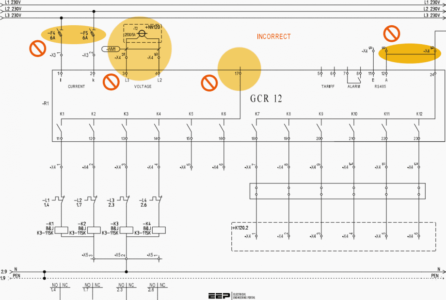
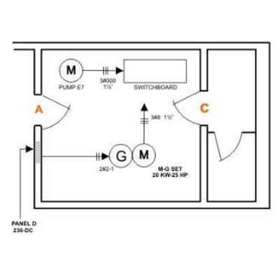
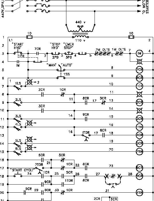
How to read electrical diagrams. Resistors are the fundamental components of electrical schematics. Solidworks electrical comes pre packaged with device libraries containing thousands of symbols 2d footprints and manufacturer parts. Repeat this process with all the circuits. For example in our diagram 2111e means that contact goes to 21 st page and the junction of 11. They are usually represented by zig zag lines with. Understanding how a schematic works opens up the whole world of electronics to you.
Wires are used to connect the components. Check out some of these tutorial to practice your new found schematic knowledge. Electrical diagrams are typically created by electrical engineers. We show our ac power source on the left with l1 and n coming out of it our switch to the top and our light to the left. To read a wiring diagram first you have to know what fundamental elements are included in a wiring diagram and which pictorial symbols are used to represent them. This method takes time but provides valuable insight into the operations of the circuit how it is connected and the basic design of the product.
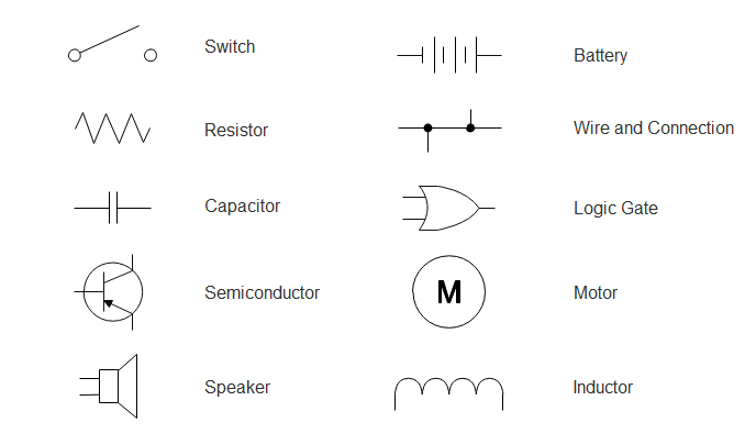
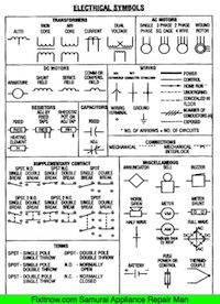
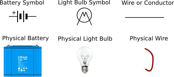
A list of electrical symbols and descriptions can be found on the electrical symbol page. The common elements in a wiring diagram are ground power supply wire and connection output devices switches resistors logic gate lights etc. Especially if you start messing around with building little electronics projects. See their number is in the horizontal axis and alphabets in the vertical axis. Follow a circuit with your finger to see where it goes and what it does. For all the electronics hobbyist wannabes this is a must read instructable.
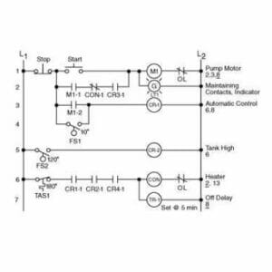
When reading an electrical diagram start at the main power source. See our engineering essentials page for a full list of cornerstone topics surrounding electrical engineering. Learn to read electrical and electronic circuit diagrams or schematics. Beginners guide how to read electrical schematics 1. In solidworks electrical complex schematics can be created in a matter of minutes and portions of the circuit copied and saved for re use. Power comes out of l2 to the switch which when open breaks the circuit preventing current flow and when closed ties the left and the right terminals of the switch together allowing current flow.
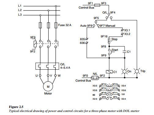
Voltage dividers this is one of the most basic. The electrical wiring diagram consists of two types such as a single line wiring diagram and a multi line wiring diagram. It is a device that stores electrical energy and usually has. There always exists the method of brute force drafting and then there are intelligent tools to bring your designs to fruition quicker. Once you know how to read an electrical schematic the next step is to design your own. The switch is connected.
Resources and going further. Thats all there is to schematic reading. In addition to reading this instructable it may be a good idea for you to read my other instructable. Read electrical wiring diagram. This instructable will show you exactly how to read all those confusing circuit diagrams and then how to assemble the circuits on a breadboard. Capacitors have different types that are in common use.
Knowing component symbols following nets and identifying common labels. To begin understanding how to read and understand electrical circuit diagrams take our basic circuit and draw it out as it would physically be wired. Circuit or schematic diagrams consist of symbols representing physical components and lines representing wires or electrical. A drawing of an electrical or electronic circuit is known as a circuit diagram but can also be called a schematic diagram or just schematic. The box is marked with the numbers and alphabets followed by the page number. Refer to the figure an electrical wiring diagram is surrounded by the rectangular box.
Gallery of How To Read Electrical Diagrams