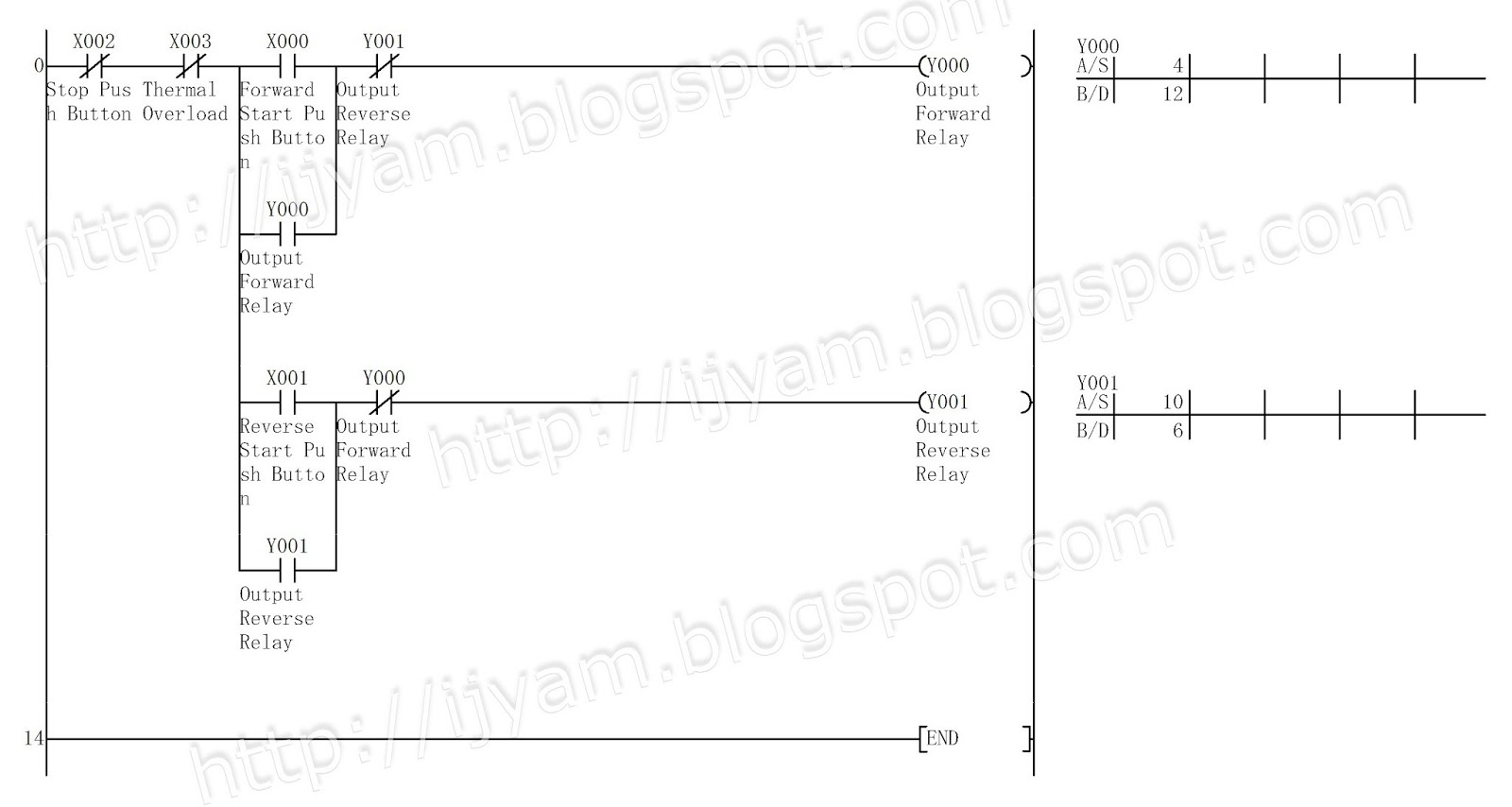
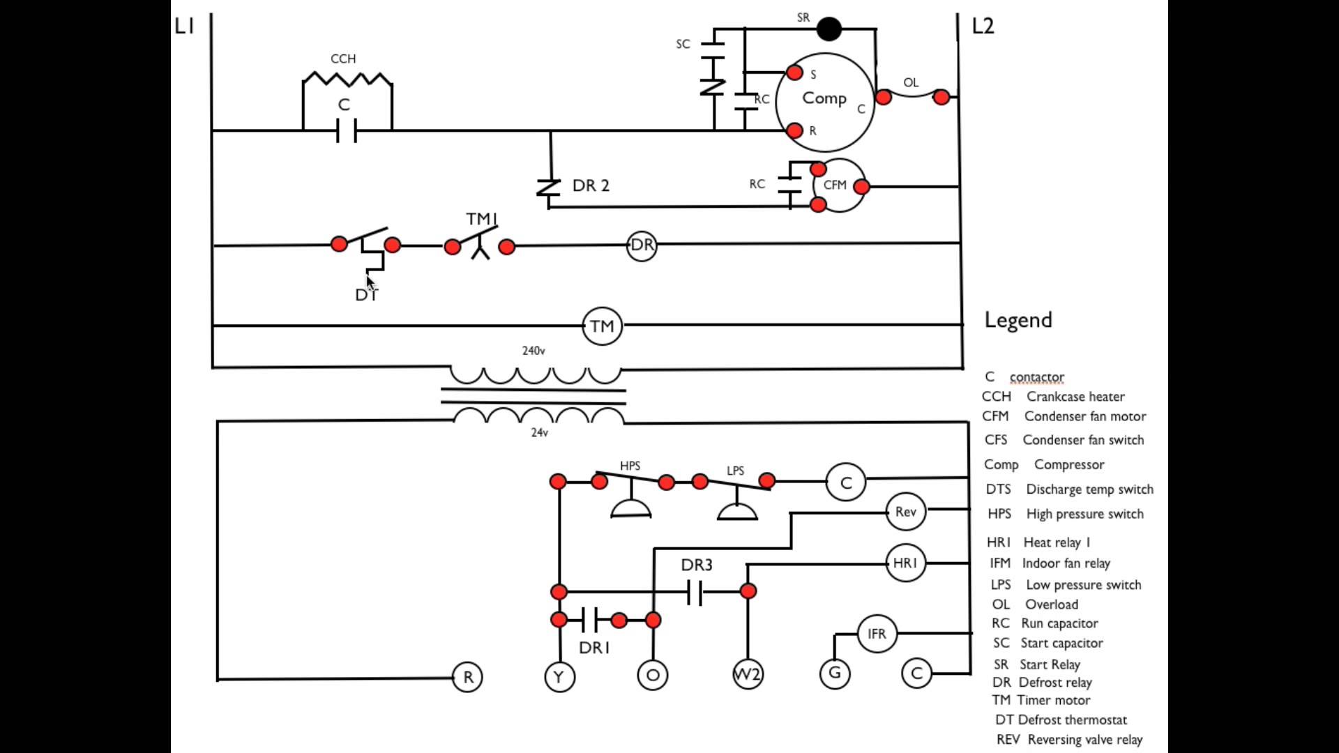
In case of power failure. Convert the given relay ladder diagram into plc system.

Vfd Control Panel Wiring Diagram Wiring Diagram
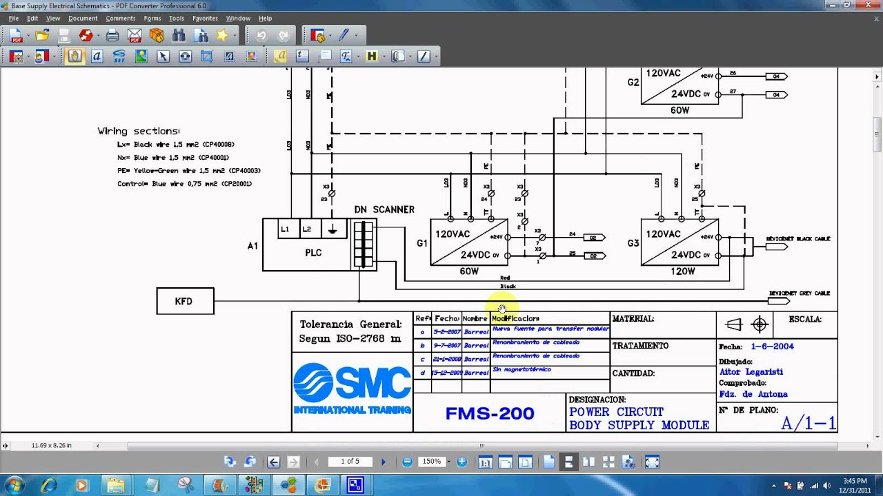
How to read plc wiring diagrams. A wiring diagram typically offers. Rslogix 500 plc training. In an industrial setting a plc is not simply plugged into a wall socket. Plc panel wiring diagram pdf. The below list shows the basic types of wiring connections available for di do ai ao signals. The top rung is read from left to right.
Plc training 44 questions and answers about plc programming. Now this battery is used to store the information. Transformers to step down ac supply voltages to lower levels. Digital input di signals. Shows which direction power flows through the circuit. 11 ipb2 ri2 r32 r2 ll lif r13 m r21 r3 ipb3 r23 li.
The electrical design for each machine must include at least the following components. Plc training 44 questions and answers about plc programming. Assortment of plc panel wiring diagram pdf. The source neutral is spliced through to. And again programming cable to program a plcthat is the battery. Plc and scada training courses.
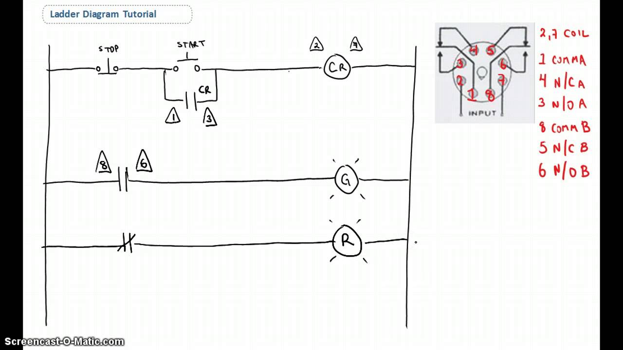
Plc ladder diagram 24v r22 r3iri pbi 1 220 vac ri. A ladder diagram is read from left to right and from top to bottom figure 3 showing the scanning motion employed by the plc. Plc wiring diagram symbols image. Note that these diagrams are without a barrier or isolator fuses and surge protector for keeping it very simple and understandable. Rslogix 500 lessons on basic bit instructions timers counters how a plc. The hot source is wired to one terminal on the switch and the other connects to the black wire running to the hot terminal on the receptacle.
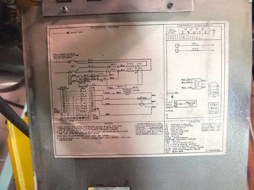
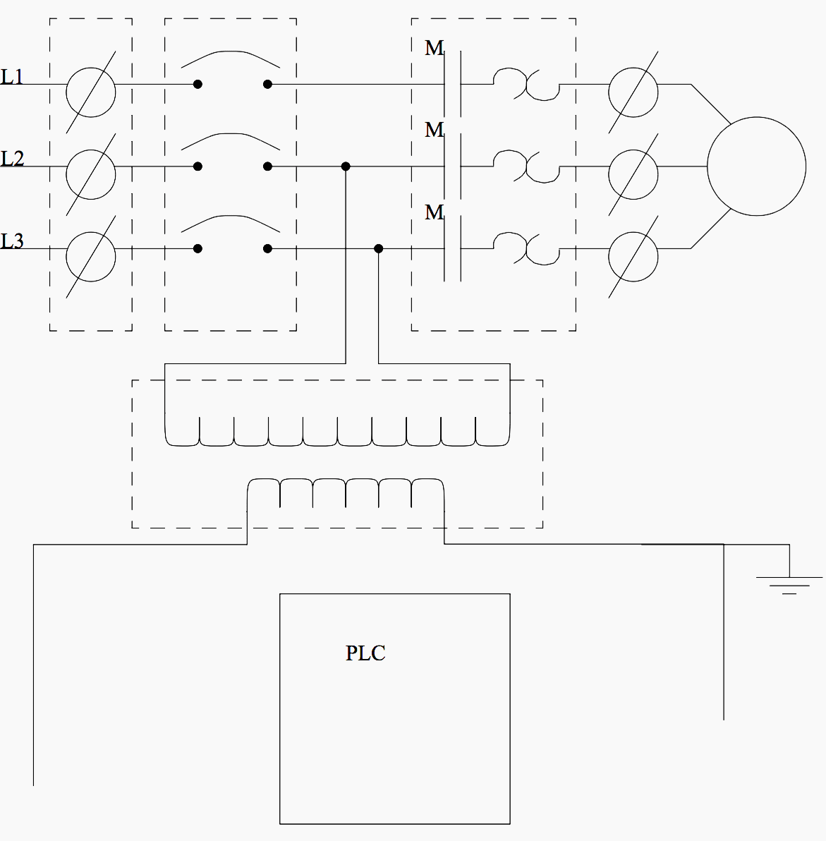
Everything inside the dashed box happens inside the plc. A wiring diagram is a simplified conventional photographic representation of an electric circuit. Now then power of vdc which is used to runpower the plc. Fuses or circuit breakers will cause power to fail if too much current is drawn. How to read these diagrams. This wiring illustrates a switched outlet circuit with the source and switch coming first.
Terminals to connect devices. In the picture without common the green points all lead to the same voltage source. Power contacts to manually enabledisable power to the machine with e stop buttons. Electrical wiring diagrams of a plc panel. Wiring a switch to an outlet. Getting familiar with rslogix 500 lessons downloading and installing the software going online with your plc.
Another plc of the company allen bradley micrologixplc wiringsimilarly we have input terminals hereoutput terminals here. Plc training how to get a job programming plcs. Plc training reading electrical wiring diagrams and understanding schematic symbols. Then the second rung down is read from left to right and so on. The picture to the right shows an example of what the wiring of a plc with 4 inputs would look like. In order to increase io points on plcs without increasing the number of connections commons are used.
This just tells you where the plc fits into the equation. Wiring diagrams of plc and dcs systems. April 28 2019 by larry a. To store the program when there is. Provide the following with complete details. This page contains several diagrams for wiring a switch to control one or more receptacle outlets including a split receptacle and multiple outlets wired together.
Figure 3 scanning the ladder program. Free wiring diagram menu. You can see some indications here when plc is powered on you can see this green light. When plc is running you can see green. It shows the elements of the circuit as streamlined shapes as well as the power as well as signal connections in between the tools.
Gallery of How To Read Plc Wiring Diagrams