How to wire fluorescent lights in series step 1. Ground fault circuit interrupters are wired in a series as a safety precaution so if the gfci receptacle trips electricity cannot reach the remaining.
Dark To Light Dsw Series Electronic Wire In Photo Control
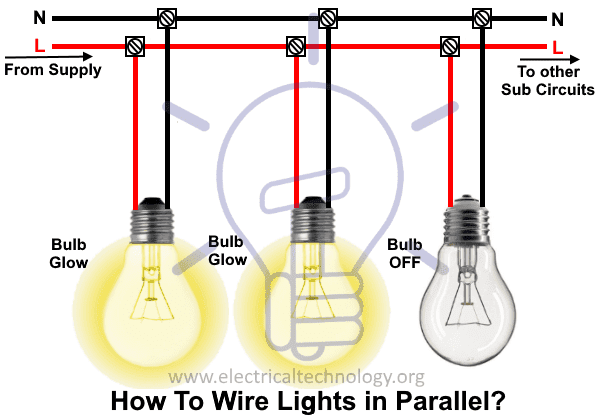
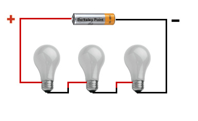
How to wire lights in series. Youll probably run that cable through the attic. Turn the electrical power off at the panel box. If you are not looking for information about wiring lights in series but rather wiring a series of lights together on one circuit the way the lights are connected is a parallel arrangement and not series. More current needed when additional light bulb added in the parallel circuit. In this post you will learn about the wiring lights series with complete explanation diagram mostly we did not wire light bulbs in series connection in our house wiring but i am just writing this post just for your understanding and to learn complete about the current and voltage pressure in series circuit and how a series circuit works and why we did not use the series lights connection. The l line also known as live or phase is connected to the first lamp and other lamps are connected through middle wire and the last one wire as n neutral connected to the supply voltage then.
In above fig all the three light points are connected in series. Cut a length of 142 nonmetallic cable nm that measures. Battery runs out quicker for dc installation. How to wire lights in series. To wire a series circuit like the one shown the positive output from the driver connects to the positive of the first led and from that led a connection is made from the negative to the positive of the second led and so on until the last led in the circuit. Following the manufacturers directions use an electrical.
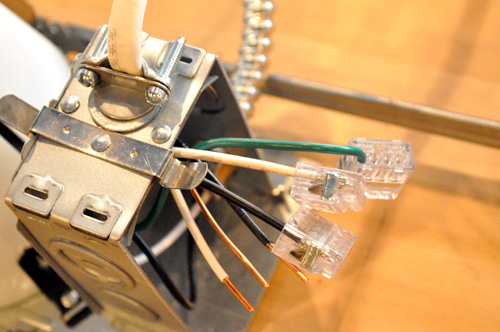
How to wire recessed lighting in parallel. If you want to add a fixture youll need an extra cable in the box that goes to that fixture. Connect the black wire to the black wire on the light the white wire to the white one on the light and the bare one to the ground wire or the ground screw. The image to the right shows an example. Wiring lights in series results in the supply or source voltage being divided up among all the connected lights with the total voltage across the entire circuit being equal to the supply voltage. More size of cable and wire is used in parallel lighting wiring circuit.
Measure the distance between each fluorescent fixture. The parallel wiring design is more complex as compare to series wiring. Each lamp is connected to the next one ie.
Gallery of How To Wire Lights In Series