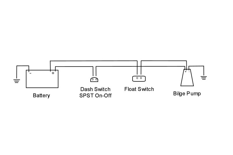
I did it just like this and the float switch dont work and there is no power to the pump at all. Thanks for reading johnson pump wiring diagram wiring library rule automatic bilge pump wiring diagram.

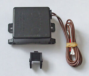
Rule Identifying The 3 Wires On The Rule Bilge Pumps
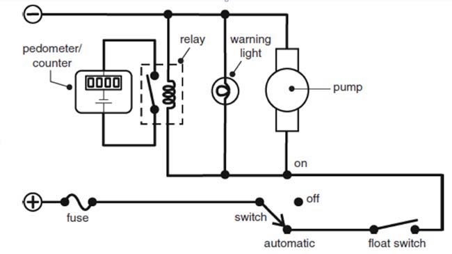
Johnson bilge pump wiring diagram. The johnson pump brownred wire goes to a switch on the dash that will power the pump in its on position so dont connect that wire to the battery. Johnson pump wiring diagram wiring library rule automatic bilge pump wiring diagram wiring diagram arrives with several easy to adhere to wiring diagram guidelines. These guidelines will likely be easy to grasp and apply. If i put a switch according to the diagram how will the pump get power from the float switch is this just auto pump with no manual tern on. Seems the float is not working as i checked it for continuity but i jumped through the plug that the float connects to and still not working. If the pump is the cycling variety it will over time wear down the battery.
Bilge auto float switch wiring bilge wire is most likely a brown color wire with a yellow trace on it. Adjusts between a 12v dc and 24v dc bilge pump without on the pump. I have a 1974 johnson 85 hp and the powershift 2 controller and were just getting into getting this boat running been sitting long time and not finding any info on the powershift 2 control box or wiring diagram for this unit. Johnson bilge pump wiring diagram with float switch 28102018 28102018 5 comments on johnson bilge pump wiring diagram with float switch digital technology that uses the patented mirus field effect detector cells producing micro electrical fields that detect disruptions caused by water and fluids. Im replacing a rule auto bilge pump with a johnson pump and the wiring makes no sense. For the bilge auto switch to work it should have power to it at all times even if the battery switch is turned off if you have a battery switch.
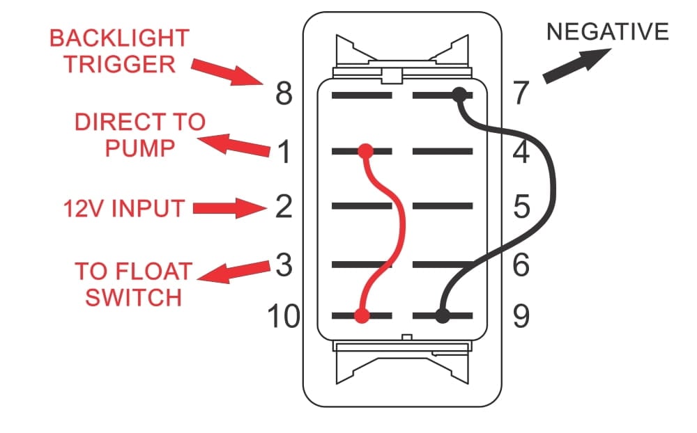
Troubleshooting bilge pump wiring to find out why bilge pump not working. 3 backlit bilge rocker switch wiring diagram. In the right hand diagram you can see how the backfeed from the float switch might come back up the manual line and. Also verified that there was 12v coming into the plug that connects to float. The pump will come on connected direct to the battery but thats it. For rule pumps the brownwhite does the same thing.
It is meant to assist each of the common consumer in developing a suitable system. Surprisingly i found both pins had 12v to ground. Rule 500 bilge pump wiring diagram wiring diagram is a simplified satisfactory pictorial representation of an electrical circuit. It shows the components of the circuit as simplified shapes and the aptitude and signal links amid the devices. Jul 16 i am having trouble wiring a johnson 3 wire electronic float switch to a 3 way switch with manual off and automatic bilge pump operationmay 31 re. Verified pump works by applying 12v direct to motor.
There are some variationssome pumps cycle periodically to check for water presence and some dont. Here we have another image best of rule automatic bilge pump wiring diagram diagrams for rule automatic bilge pump wiring diagram featured under johnson pump wiring diagram wiring library rule automatic bilge pump wiring diagram. Now believe that i understand what was happening as i think the toggle switch for on for the. Of the three bilge pump switches the only one thats not extremely simple is the backlit automanual bilge pump switch. We hope you enjoyed it and if you want to download the pictures in high quality simply right click the image and choose save as. If it is a fully automatic bilge pump the rule brown wire will go to the battery and the black wire goes to ground.
Learn more about how our awesome backlit switches work here even that one is still pretty straight forward though here are some diagrams that show the single jumper required on the back of the switch. So hopefully can pick the.
Gallery of Johnson Bilge Pump Wiring Diagram