Red and blue wires link traveler terminals of both switches. Damp condensation rot and woodworm.
Switches
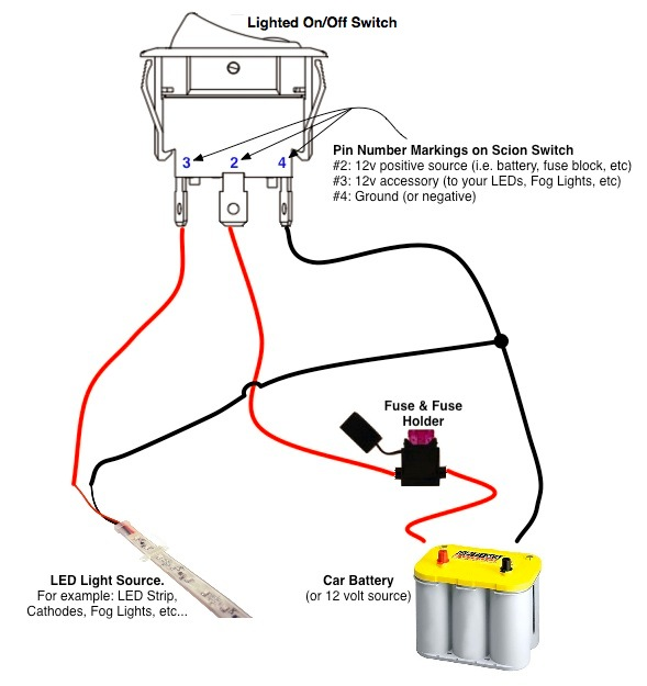
Lighted switch wiring diagram. And when you move or. Each component should be placed and linked to different parts in specific way. Garages sheds and outbuildings. Light switch wiring diagram. Wiring diagram also provides. Skip to primary sidebar.
Explanation of wiring diagram 1 switch wiring shows the power source power in starts at the switch box. The other end of the lamp is connected with neutral line of ac power supply. Three wire cable runs between the switches and 2 wire cable runs to the light. Illuminated rocker switch wiring diagram 120v illuminated rocker switch wiring diagram 12v illuminated rocker switch wiring diagram 240v illuminated rocker switch wiring diagram every electrical structure consists of various diverse pieces. A clear wiring diagram showing how to connect up a timed fan and install a extractor fan with timer. First i want to highlight those things which we use for doing this connection.
Otherwise the structure will not work as it ought to be. Circuit electrical wiring enters the switch box the black wire power in source attaches to one of the switch screw terminals. The source is at sw1 and 2 wire cable runs from there to the fixtures. Pin1 of both the switches are connected with the phase or live wire and pin2 of both the switches are connected with the one end of the lamp. Doors windows and conservatories. The hot and neutral terminals on each fixture are spliced with a pigtail to the circuit wires which then continue on to the next light.
As you can see in the schematic diagram of 2 way switch circuit below the common of both the switches are short circuited. Floors walls ceilings and lofts. After turning off the circuit breaker and stripping an inch of insulation from the ends of all the wires in the box test the box to confirm that power is off with a non contact voltage tester. Brick block marsonary and concrete. From this post you complete learn about light switch wiring with a simple diagram and video tutorial in english language. Fencing decking paving and patios.
You may be capable to know precisely once the tasks needs to be accomplished which makes it much easier for you personally to correctly handle your time and effort. This 3 way light switch wiring diagram shows how to do the light switch wiring and the light when the power is coming to the light fixture. Connect one of the black wires to the top brass terminal and the. The black and red wires between sw1 and sw2 are connected to the traveler terminals. Multiple light wiring diagram this diagram illustrates wiring for one switch to control 2 or more lights. Skip to main content.
And this will be complete guide of wiring a light switch. Skip to primary navigation. Additionally wiring diagram provides you with enough time body in which the projects are for being completed. Wiring diagram 3 way switch with light at the end in this diagram the electrical source is at the first switch and the light is located at the end of the circuit. The wiring of light switch is very simple connection but before we start the wiring connection. The black hot wire connects to the far right switchs common terminal.
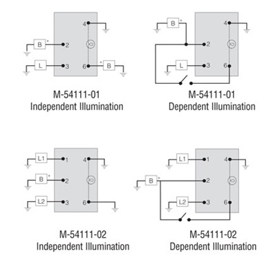
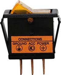
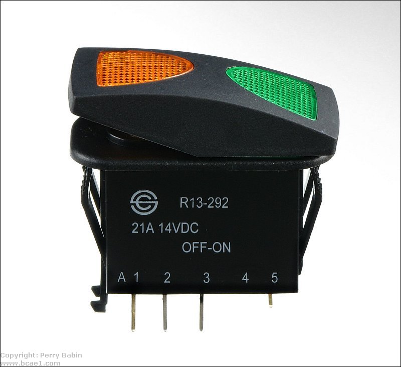
Illuminated rocker switch wiring diagram wiring diagram 5 pin rocker switch wiring diagram. We use a one way switch single way switch which is normally open contacts internally. In this diagram power enters the fixture box. 5 pin rocker switch wiring diagram wiring diagram 5 pin rocker switch wiring diagram. To wire an illuminated light switch and this is true for any conventional single pole single throw switch you need only the hot wire that comes from the power source and the one that goes to the fixture that the switch controls.
Gallery of Lighted Switch Wiring Diagram