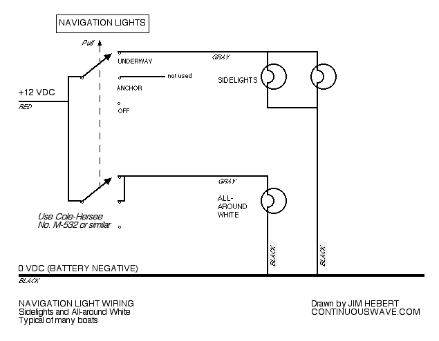
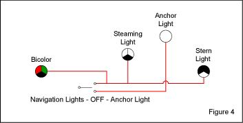
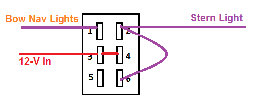
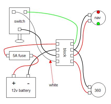
When the navanc rocker switch is in the up position both the redgreen and the white lights are on. When the switch is in the anchor position you want only the white stern light to be on.

Nav Light Wiring Diagram H1 Wiring Diagram
Nav light switch wiring diagram. My switch doesnt have as many terminals and there is only one power wire for the combined anchorstern light. Just click the wiring diagrams. Navigation light output terminal 3. Top row right white stern light and short jumper wire. A red and green forward navigation light and a white stern or high point light. If your nav lights are on a separate circuit with a spst toggle the task is very easy.
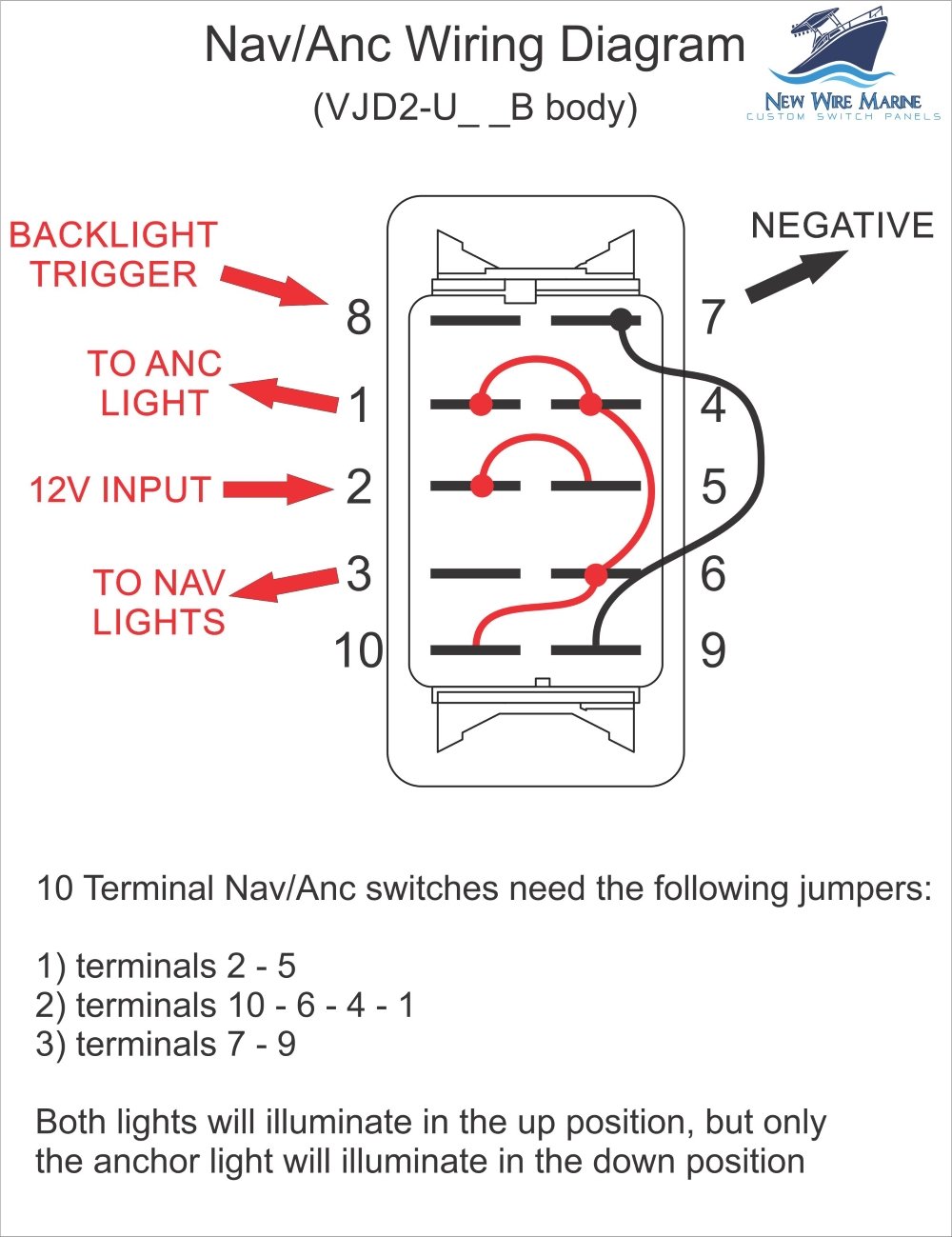
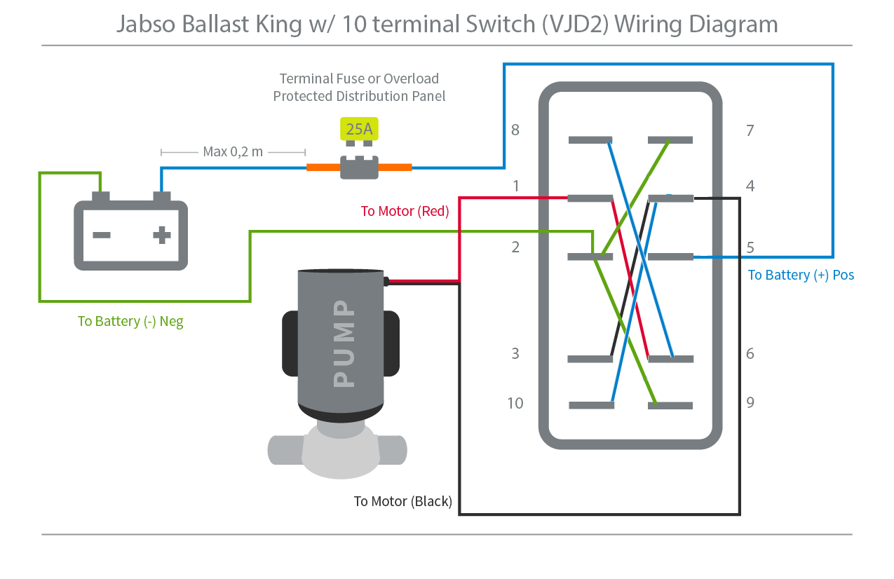
We have wiring diagrams and wiring guides on how to wire a 10 terminal navancher on off on 3 way carling contura rocker switch as well as a wiring diagrams in how to wire a 10 terminal bilge auto manual on off on 3 way carling contura rocker switch for more on how to wire a bilge pump check this out we also have a general dpdt wiring diagram for powering two loads using an on off on 3 way carling. From the back this switch will have three rows of terminals with two terminals on each row. Provides power to anchor light when switch is up provides power to both sides of dpdt switch in from backlight circuit to negative from source breaker or fuse to load 2 anc lights to load 1 nav lights external interfaces. Take the ground from the compass light and attach it to the common ground bus under the helm then take the red wire from the compass light and attach it to the post on the switch that has no power when the lights are off and ignition is on. As you said when the switch is in the navigation position you want the redgreen light and the white stern light to be on. 12v input terminal 2 and 5.
The section below has wiring diagrams the are specific to marine rocker switch panels. Anchor output terminal 1. Fully explained wiring instructions complete with a picture series of an installation and wiring diagrams can be found here in the gfi and light switch area here in this website. On the ops wiring diagram shouldnt either 8 or 9 be identified as stern light. Then when you turn the nav light switch on the nav lights. Here are your electrical connections.
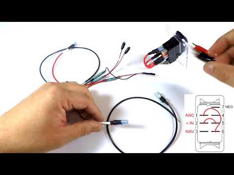
That wire is powered in the navigation and anchor positions of one switch. Top row left no connection. Navigation powers the combination light and the stern light anchor powers. Pin 8 pin 2 pin 3 pin 1 backlight circuit in power in going to loads nav light power switch up. Negative source terminal 7 place jumper between terminals 2 5 and 1 6 see wiring diagram a hard copy of the wiring diagram will be shipped with this switch. This nav anc rocker switch has 7 terminals on the back.
Gallery of Nav Light Switch Wiring Diagram