This switch will light the bottom light when it is down and the upper light when it is up. This nav anc rocker switch will replace any carling v series or contura style rocker switch.
Navigation Light Wiring For Dual Stations Boat Design Net
Navigation light switch wiring diagram. Crimp a three wire connector onto both ends of the red wire. Clip the red wire in the cable. If wired correctly the up position indicates on both lights as it should. This guide provides instructions rocker switch wiring diagrams and information for multiple carling v series rocker switches with 10 terminals and two independent lights. Our navigation anchor rocker switch has two indicator lights that illuminates when the switch is on in either position. For marine applications an extremely common use for this vjd1 switch is as a navigation and anchor light switch.
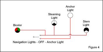
Multiple light wiring diagram this diagram illustrates wiring for one switch to control 2 or more lights. Take the ground from the compass light and attach it to the common ground bus under the helm then take the red wire from the compass light and attach it to the post on the switch that has no power when the lights are off and ignition is on. Bottom row right short jumper wire that is connected to the top row right terminal. Specialty wiring and instructional guide for. Bottom row left redgreen bow light. Then when you turn the nav light switch on the nav lights.
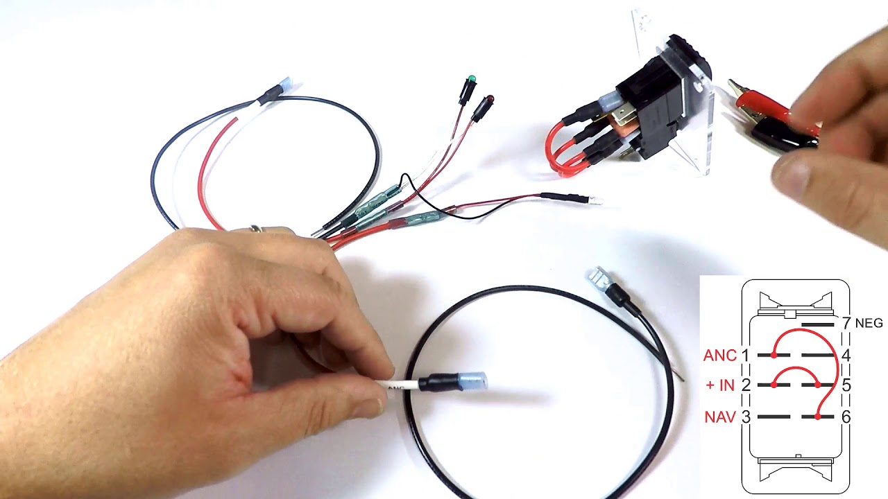
Middle row left 12 power. In this video wiring guide we show how to wire a 7 terminal vjd1 d66b rocker switch to operate a boats navigation and anchor lights. Variety of pontoon boat wiring schematic. If the switch has a seventh terminal on the top right connect a ground wire to this. In this extremely common configuration a single switch is. Pull the roll of boat cable from the switch to the first nav light.
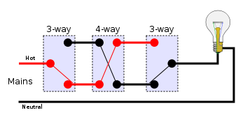
Middle row right 12 power. Strip a half inch of insulation from the wire. The hot and neutral terminals on each fixture are spliced with a pigtail to the circuit wires which then continue on to the next light. How to wire as a navanc switch. It reveals the parts of the circuit as simplified shapes as well as the power and signal links between the devices. A wiring diagram is a simplified conventional photographic representation of an electrical circuit.
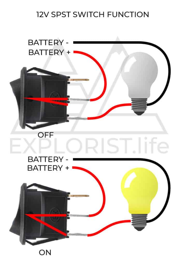
Push the navigation lights red wire into the remaining opening of the three wire connector and crimp the connector. The source is at sw1 and 2 wire cable runs from there to the fixtures. Use this guide when you want an on off on rocker switch to provide power to two loads when in the up position and only one of. Weve created a short video explaining how to do this. If your nav lights are on a separate circuit with a spst toggle the task is very easy.
Gallery of Navigation Light Switch Wiring Diagram