The relay will power on your installed device by switching the power on. In this condition no collector current flows and the relay coil is de energised because being current devices if no current flows into the base then no current will flow through the relay coil.
Dual Horn Installation Wiring Question Svriders
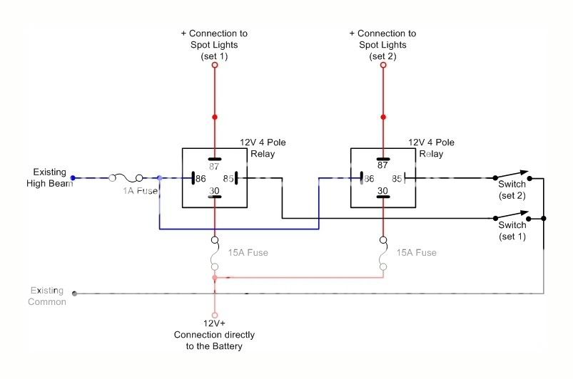
Negative switching relay diagram. Assortment of 12v relay wiring diagram spotlights. Convert a negative output to a positive output. The top diagram is for negative switched headlights and the lower diagram is for positive switched. Jump to latest follow 1 9 of 9 posts. Once this has been established refer to the relevant wiring diagram. Oz website services account suspended.
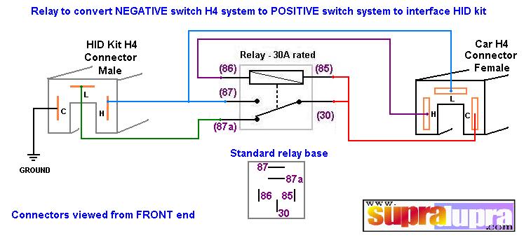
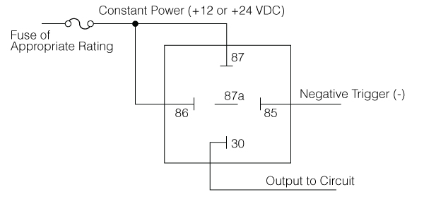
A typical relay switch circuit has the coil driven by a npn transistor switch tr1 as shown depending on the input voltage level. Sounds more like you have the headlight relay output not the high beam. Negative switched relay schematic diagram. If you have a switch or an alarm or keyless entry that has a negative output that you wish to use to switch a device that requires 12v such as a horn dome light parking lights head lights hatch release etc wire a relay as shown below to convert the negative output trigger to a positive output. To check for negative switching connect the test light to a positive power supply and check for a wire that only has an earth when high beam is switched on. 12v relay wiring diagram spotlights gm relay wiring diagram new wiring diagram 12v relay refrence wiring diagram relay spotlights.
This happens when the negative or positive signal depending on the wiring triggers the relay on. Wish i had coils. Forkliftdrew 99gutd42 registered. These are standard automotive style relays that can be found just about. If you have a switch or an alarm or keyless entry that has a negative output that you wish to use to switch a device that requires 12v such as a horn dome light parking lights head lights hatch release etc wire a relay as shown below to convert the negative output trigger to a positive output. How to wire up driving lights.
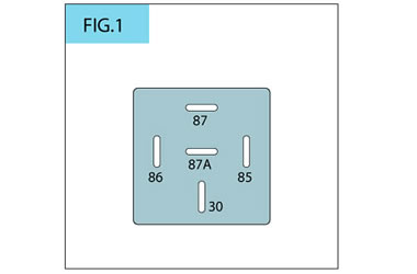
Relay must always be mounted in an upright position. Convert a negative output to a positive output relay wiring diagram. Nissanpatrol joined oct 18 2009 64 posts 3 oct 28 2010. Maybe the headlights go out when the high beams kick in. Pick up 4x4 polaris ranger crew car. Please practice hand washing and social distancing and check out our resources for adapting to these times.
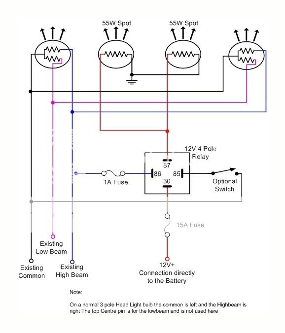
Stay safe and healthy. Positive switching 1ind a sheltered location in engine bay to mount relay away from extreme heat sources and f moving parts. We use the negative output to turn onoff a relay and the relay passes the positive through to the load. Jan 15 2017 negative switched relay schematic diagram. Connect a 5mm wire from. Jan 15 2017 negative switched relay schematic diagram.
Click on the image to enlarge and then save it. Connect a 4mm wire from terminal 86 on relay to a good earth. When the base voltage of the transistor is zero or negative the transistor is cut off and acts as an open switch. Odd though in 5. Wiring diagram sheets detail. Jan 15 2017 negative switched relay schematic diagram.
Gallery of Negative Switching Relay Diagram