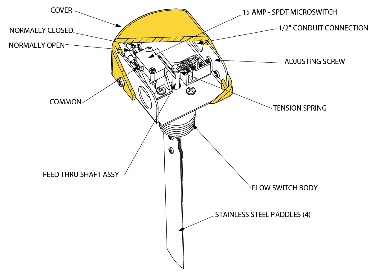
Normally open and normally closed for instance the following diagram shows a normally open pushbutton switch controlling a lamp on a 120 volt ac circuit the hot and neutral poles of the ac power source labeled l1 and l2 respectively. Take these two rules and remember them.
Assembly Manual
Normally open switch diagram. 2006 harley davidson ultra classic wiring diagram. It has three terminals. Which wire is positive black or red. Old honeywell thermostat wiring diagram. How to wire 10 3 with ground. 50 out of 5 stars 3.
What is a single pole double throw spdt switch. 5 coupon applied at checkout save 5 with coupon. When a momentary switch is not actuated its in a normal state. Thermal magnetic switch info. The no normally open connection of the relay is not connected until the relay turns on. Ceiling fan with light australia.
Current locksets that offer an rx or lx switch can operate in either state but the product you are tying them into usually dictates which type of state is required. What is the difference between normally open and normally closed. Recessed wired window garage contact sensor alarm magnetic reed switch white hc 34a 10pcs. Dip dual in line package encapsulated switches eg. Dip dual in line package encapsulated switches info. A three way switch is simply a normally open and normally closed switch in which one side of each contact is tied together.
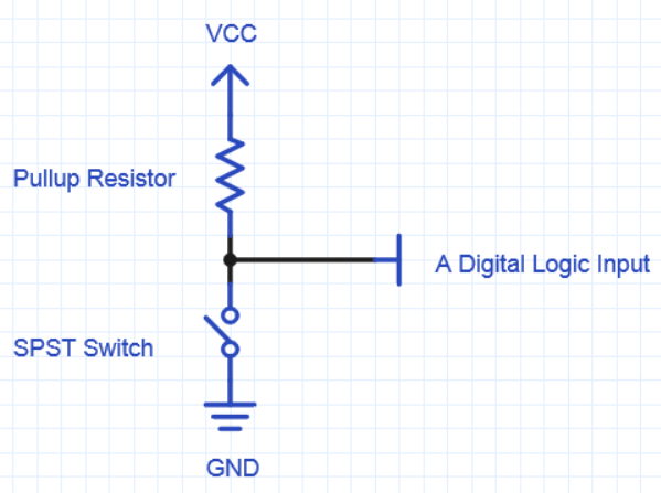
Normally open and normally closed switch diagram. Only 10 left in stock order soon. A common com which is the left terminal in the image below a normally closed nc terminal which is the top right terminal in the image below and a normally open no terminal which is bottom right terminal in. 4 way circuit diagram. Mercury switch inclination or motion detector info. Contact driven by a pulse counter symbols.
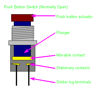
Get it as soon as tue jul 7. 45 out of 5 stars 19. Float switch level switch fluid info. When you activate a normally open actuator the input bit will switch to 1. In a push button type switch rx or lx in which the contacts remain in one state unless actuated the contacts can either be normally open abbreviated no or no until closed by operation of the switch or normally closed nc. Or nc and opened by the switch action.
Open thermal switch. 12v transformer wiring diagram. This is the difference between normally open and normally closed. It acts as a normally closed nc switch and in case of enhancement mode the channel is not formed initially ie. In the default state inactivated of a normally open actuator the input bit is 0. In an industrial environment we call this a single pole double throw spdt switch.
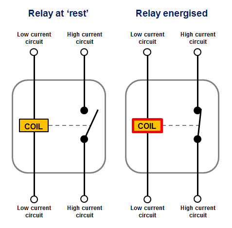
Diagrams will show how multiple relays one relay or another or just one relay can control your device. Switch with neon lamp incorporated. When a button is open until actuated its said to be normally open abbreviated no. When a relay is off the common is connected to the nc normally closed. All examples shown are for spdt single pole double throw relays which includes any of the 5 10 or 20 amp relays on this site. Home electrical wire size chart.
Normally closed input actuators. More buying choices 574 2 new offers uxcell nc. We can tell this switch is a normally open no switch because it is drawn in an open position. When you actuate an no switch youre closing the. How does a 3 way switch work. The main difference between enhancement mode mosfet and depletion mode mosfet is that in depletion mode the channel is already formed ie.
Cylewet 15pcs reed switch with gilded lead normally open no magnetic induction switch electromagnetic for arduino pack of 15 cyt1065. Normally open input actuators. A normally open no switch. Depending on how the button is constructed its normal state can be either an open circuit or a short circuit. Foot operated switch. Relay logic the com common connection of a relay is the part of the relay that moves.
Get it as soon as.
Gallery of Normally Open Switch Diagram