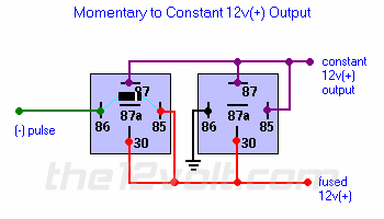
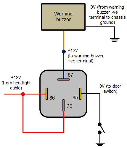
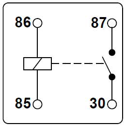
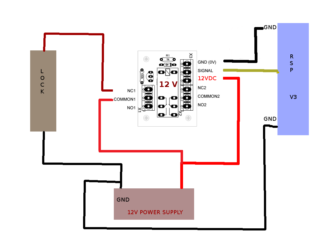
A wiring diagram is a simplified traditional pictorial depiction of an electrical circuit. The middle pin is the common pin.
Understanding Relays Amp Wiring Diagrams Swe Check
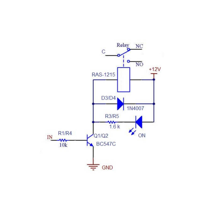
Relay circuit diagram 12v. The purpose of an automotive relay is to automate this power to switch electrical circuits on and off at particular times. You can also notice a diode connected across the coil of the relay this diode is called the. The operating voltage of the coil and high current circuits. A 1kω resistor a 100kω variable resistor and another 1kω resistor are connected in series between the supply and ground. The wiper of the variable resistor is connected to the positive terminal of a 1000µf capacitor. The square relay pinout shows how the relay socket is configured for wiring.
The wiper terminal of the. The top and bottom pins on the left are the relay coil pins. The lamp hot wire from the mains supply is connected to one terminal of the lamp. 1n4728a 33v zener 1. Relays take a relatively small amount of power to operate the relay coil but the relay itself can be used to control motors heaters lamps or ac circuits which themselves can draw a lot more electrical power. 100µf 25v 1.
1000µf 25v 1. All four relays are connected with arduino at 8910 and 11th pins in1 in2 in3 and in4 and 1 12v adapter is used for powering the circuit. 100 kω pot 1. Circuit design of time delay relay. Relays are switches controlled by electrical power like another switch computer or control module. Since the relay has 12v trigger voltage we have used a 12v dc supply to one end of the coil and the other end to ground through a switch.
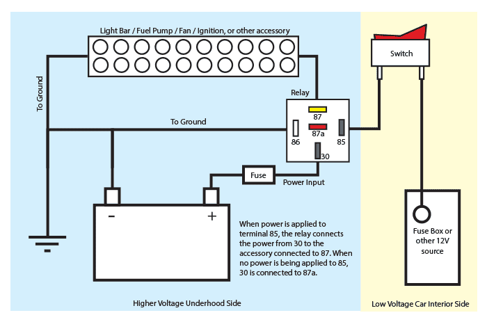
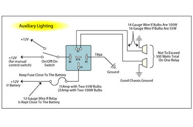
The relay type must be selected according to the circuit used. For switching we are using a transistor as a switching device. Coming to the load part ie. Single pole double throw spdt relay diagram. Typically 12v for passenger vehicles and small craft but also available in 6v for older vehicles and 24v for commercial applications both auto and marine. We have connected 220vac bulb at the terminal block of the pcb board and ac supply is also applied to the board.
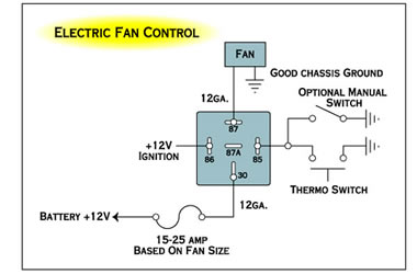
5v and gnd and connect the control signal from arduino to control pin on the relay board. Here we look at relay switch pin diagram and the different kinds of relay switches. 12v relay 1. In the case of dual ratings the normally closed circuit is the lower of the. 12v relay connection diagram read our guide to relays found in vehicle electrical systems. The above diagram is for relay triggering circuit.
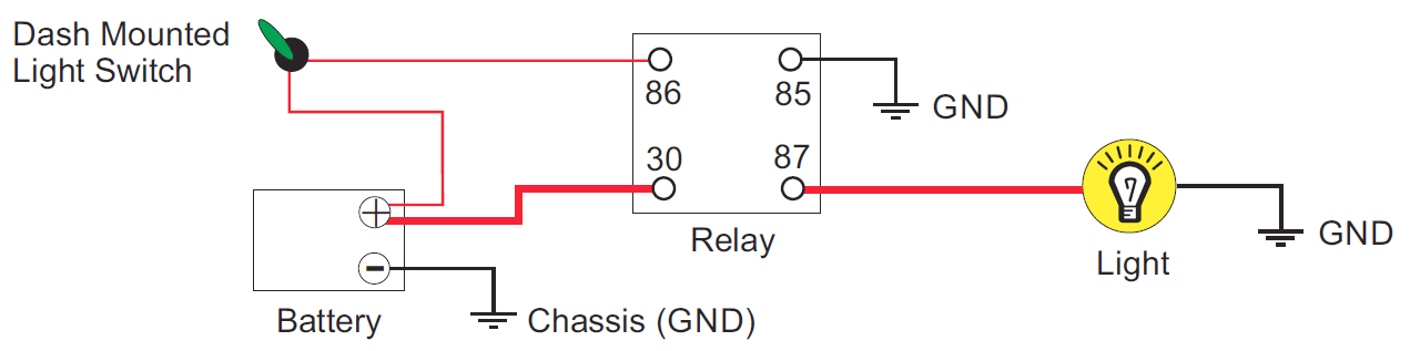
Relays control circuits by opening and closing contacts in another circuit. The bottom right pin is the normally closed switched pin. The relays can be varied as magnetic relays tongue contacts thermal relays overcurrent protection relays. For example overcurrent protection relays can be used to tie the tongue contact if the switch is to be switched on by the magnetic effect and to limit the high current. However the real benefit behind a relay is more than just automation. Assortment of 12 volt relay wiring diagram.
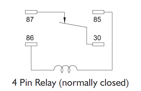
It reveals the components of the circuit as simplified shapes and also the power and signal connections in between the tools. The terminals are coil coil com and no and nc. This is the current carrying capacity of the high current circuits and is normally between 25a and 40a however it is sometimes shown as a dual rating on changeover relays eg. The top right pin is the normally opened switched pin. Most relay modules whether 5v or 12v will come with the aforementioned connection and hence all you need is to give power supply to the relay module ie. 12v dc relay switches are the best solution for full voltage.
We will examine the relay types in more detail below. They also provide the ability to switch multiple circuits including different voltage types within the same relay at the same time. Although the circuit diagram explains the detailed connections practically we didnt need to make all the connections.
Gallery of Relay Circuit Diagram 12v