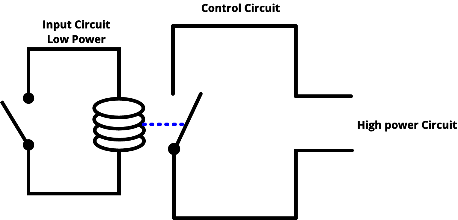
As shown the power source is given to the electromagnet through a control switch and through contacts to the load. An iron core is surrounded by a control coil.
Ac Relay Wiring Liar Gandul1 Sachse Energieberatung De
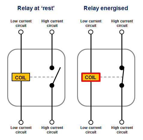
Relay circuit diagram and operation. Carefully measure those logic states to verify the accuracy of your analysis. A movable armature consists of a spring support or stand like structure connected to one end and a metal contact connected to another side all these arrangements are placed over the core such that when the coil is energized it attracts the armature. The relays can be varied as magnetic relays tongue contacts thermal relays overcurrent protection relays. Draw the schematic diagram for the relay circuit to be analyzed. The electromechanical relay can be defined as an electrically operated switch that completes or interrupts a circuit by physical movement of electrical contacts into contact with each other. When current starts flowing through the control coil the electromagnet starts energizing and thus intensifies the magnetic field.
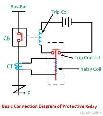
Although many different types of relay. But instead of manual operation a relay is applied with electrical signal which in turn connects or disconnects another circuit. For example overcurrent protection relays can be used to tie the tongue contact if the switch is to be switched on by the magnetic effect and to limit the high current. Thus the upper contact arm starts to be attracted to the lower fixed arm and thus closes the contacts causing a short circuit for the power to the. Check the accuracy of the circuits construction following each wire to each connection point and verifying these elements one by one on the diagram. Let us see the internal parts of this relay before knowing about it working.
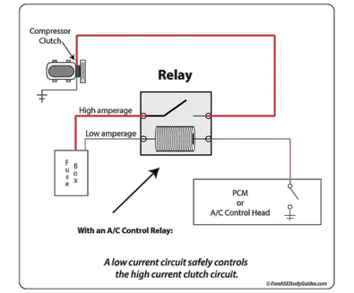
The relay is an electromechanical switch used as a protecting device and also as a controlling device for various circuits equipments and electrical networks in a power system. The relay type must be selected according to the circuit used. Construction of relay and its operation. Unlike schematic diagrams where the association between relay coils and relay contacts is represented by dashed lines ladder diagrams associate coils and contacts by label. A 230v ac supply is provided to the load in this case the load is represented with a lamp. Analyze the circuit determining all logic states for given input conditions.
Relays can be of different types like electromechanical solid state. Carefully build this circuit on a breadboard or other convenient medium. Electromechanical relays are frequently used. Relay coils are drawn as circles with relay contacts drawn in a way resembling capacitors. Symbols also differ a bit from common electronics notation. We will examine the relay types in more detail below.
The movable armature is generally. The following figure shows how a relay looks internally and how it can be constructed on a casing a core with copper windings forms a coil winded on it is placed. If there are any errors carefully check your. The diagram shows an inner section diagram of a relay. Sometimes you will find relay contacts labeled identically to the coil eg. Switches are generally used to close or open the circuit manually relay is also a switch that connects or disconnects two circuits.
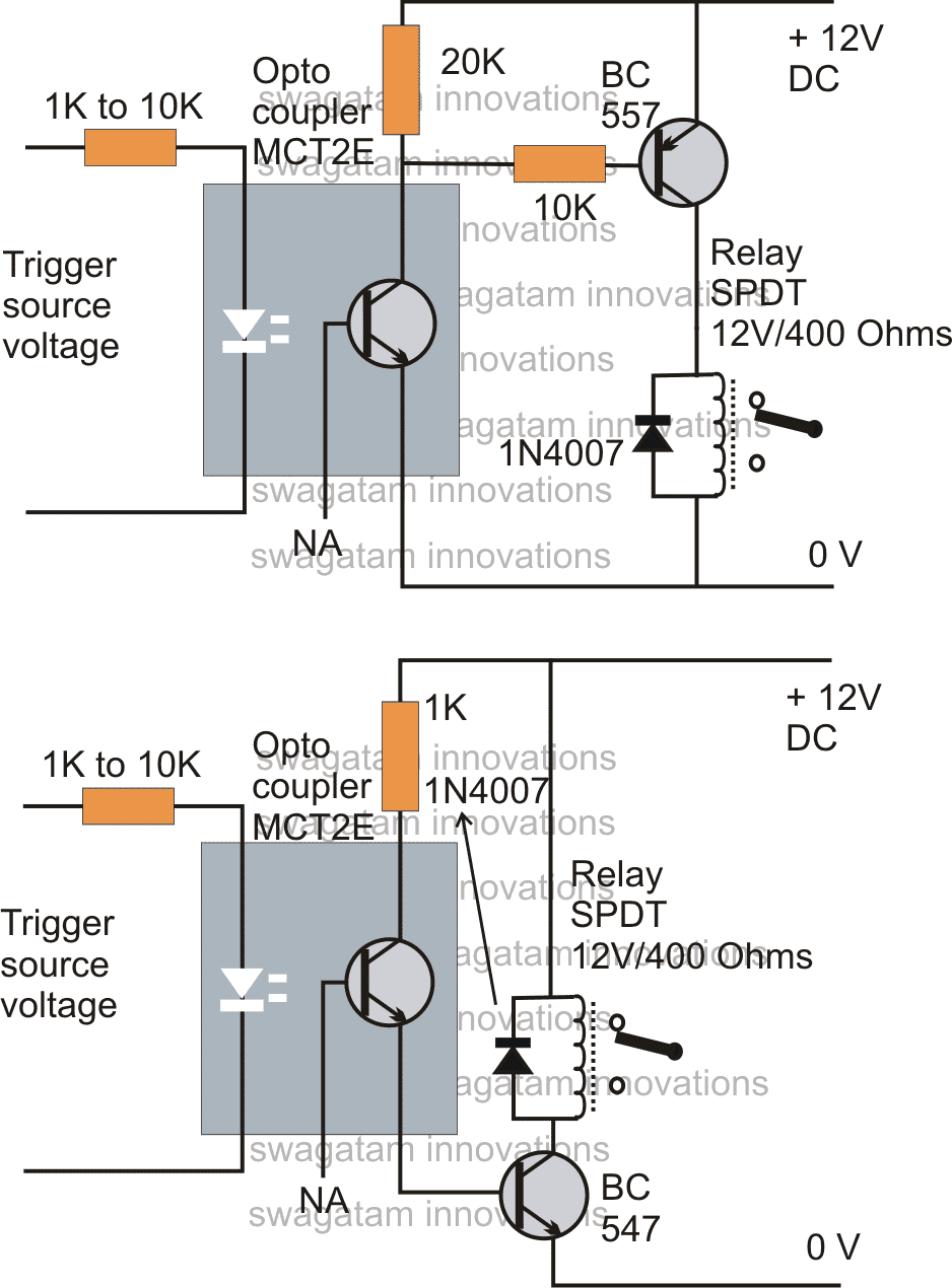
Coil labeled cr5 and all contacts for that relay also labeled cr5 while. The light sensor circuit is an electronic circuit designed using light sensor ldr darlington pair relay diode and resistors which are connected as shown in the light sensor circuit diagram. Light sensor circuit working operation.
Gallery of Relay Circuit Diagram And Operation