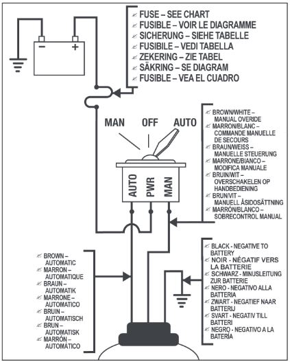
Injunction of 2 wires is generally indicated by black dot on the intersection of 2 lines. One gray wire from the float switch connects to the solid brown positive wire from non automatic bilge pump.

Wiring Diagram For Float Switch Diagram Base Website Float
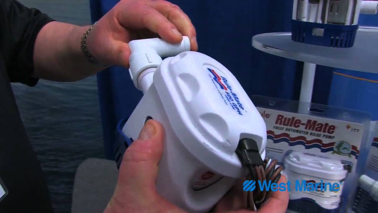
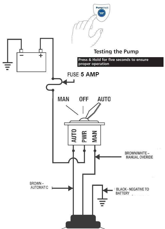
Rule automatic bilge pump wiring diagram. All wires and connections must be above the bilge water level. The pump checks for water every 2 ½ minutes by running for a second and measuring load against the impeller. Includes comprehensive user manual with installation instructions and wiring diagram. It reveals the parts of the circuit as streamlined shapes as well as the power and also signal links in between the gadgets. Learn more about how our awesome backlit switches work here even that one is still pretty straight forward though here are some diagrams that show the single jumper required on the back of the switch. Once power is supplied starting and stopping is completely automatic.
In the right hand diagram you can see how the backfeed from the float switch might come back up the manual line and. T auto gph bilge pump ¾. Rule 2000 bilge pump wiring diagram two position panel switch. It shows the components of the circuit as simplified shapes and the aptitude and signal links amid the devices. 3 backlit bilge rocker switch wiring diagram. Rule automatic bilge pump wiring diagram rule 1100 automatic bilge pump wiring diagram rule 1500 automatic bilge pump wiring diagram rule 500 gph fully automatic bilge pump wiring diagram every electric structure is composed of various diverse components.
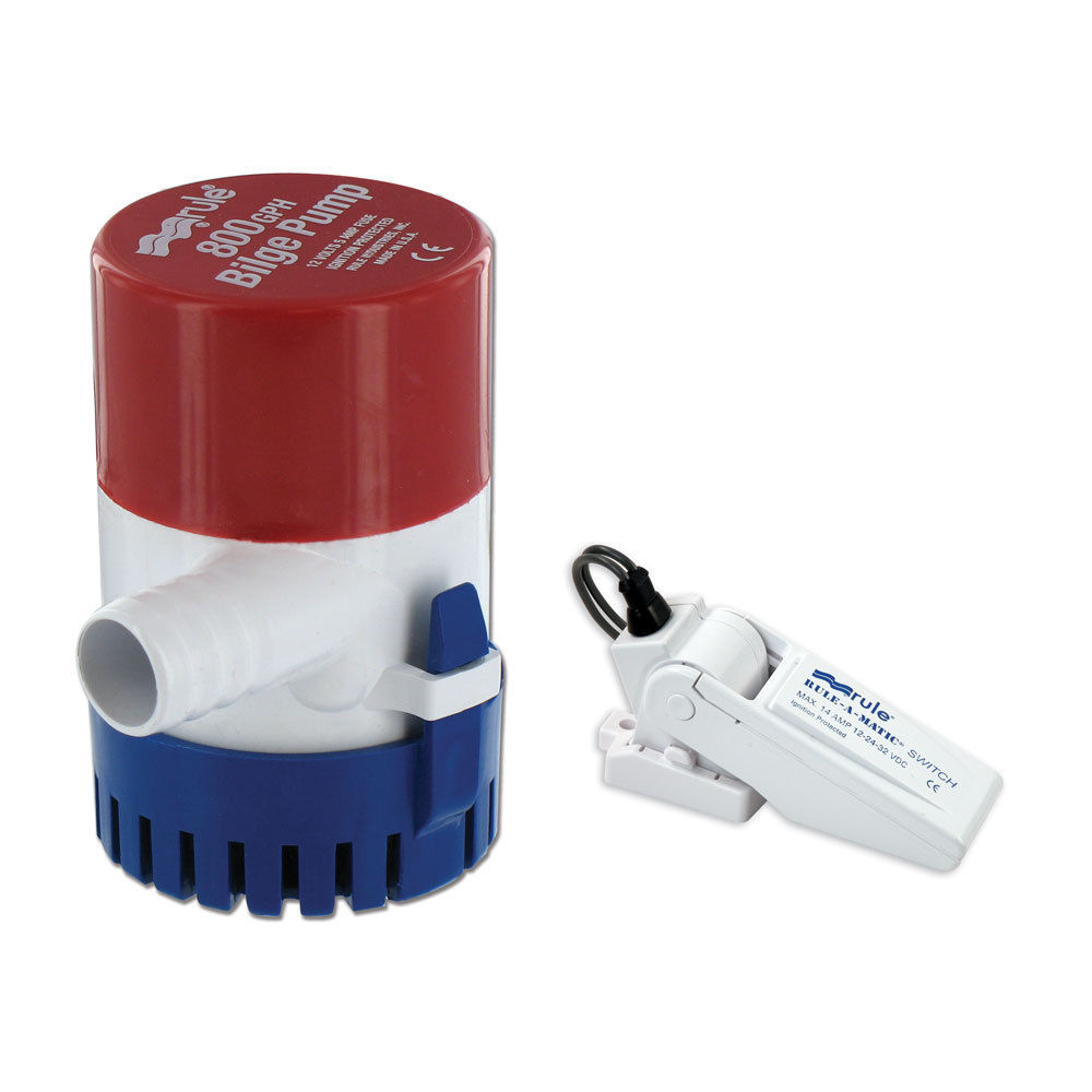
Rule 1100 gph automatic bilge pump wiring diagram collection assortment of rule 1100 gph automatic bilge pump wiring diagram. Rule fully automatic bilge pumps manual. It can not be used for by marine sealant. Automatic bilge pumps offer standard action activated by float switch. A wiring diagram is a streamlined conventional photographic depiction of an electric circuit. However it does not imply connection between the wires.
Thereafter it resumes its 2 ½ minute check cycle. Each component ought to be placed. Rule 500 bilge pump wiring diagram wiring diagram is a simplified satisfactory pictorial representation of an electrical circuit. Sometimes the wires will cross. If water is present the pump remains on until the water is removed. The third wire needs.
According to earlier the lines at a rule automatic bilge pump wiring diagram signifies wires. Through advanced electronic technology rule automatic bilge pumps eliminate the need for a separate switch to activate the pump. Auto bilge pump can only be used for pumping water. With this kind of an illustrative manual you are going to be able to troubleshoot avoid and full your projects easily. Rule automatic bilge pump wiring diagram you will need a comprehensive expert and easy to understand wiring diagram. Of the three bilge pump switches the only one thats not extremely simple is the backlit automanual bilge pump switch.
Gallery of Rule Automatic Bilge Pump Wiring Diagram