3ø wiring diagrams 1ø wiring diagrams diagram er9 m 3 1 5 9 3 7 11 low speed high speed u1 v1 w1 w2 u2 v2 tk tk thermal overloads two speed stardelta motor switch m 3 0 10v 20v 415v ac 4 20ma outp uts diagram ic2 m 1 240v ac 0 10v outp ut diagram ic3 m 1 0 10v 4 20ma 240v ac outp uts these diagrams are current at the time of publication. Wireing 208 motor starter diagram from electric fan schematic diagram source46volgitarrenapothekede goodman heat sequencer wire diagram wiring diagram paper from electric fan schematic diagram source310stawinski pflegevermittlungde.

Ceiling Fan Wiring Schematic Diagram H1 Wiring Diagram
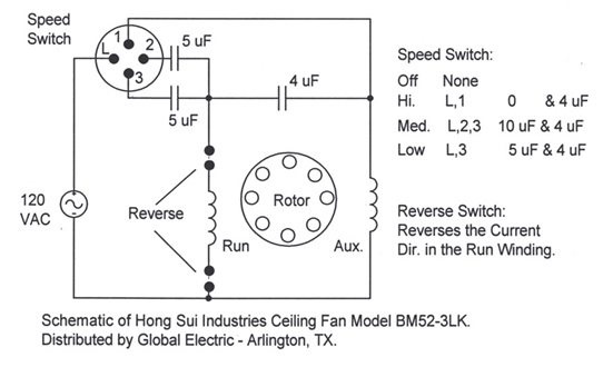
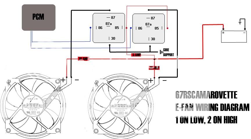
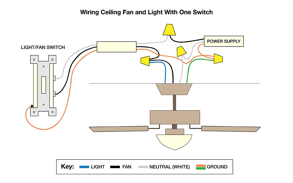
Schematic diagram of electric fan. Pick the diagram that is most like the scenario you are in and see if you can wire up your fan. It has a 3 speed fan motor. Take a closer look at a ceiling fan wiring diagram. Or a single relay could be used to control both fans. Need step by step instructions on replacing ceiling fan. With the below wiring diagrams you can install 90 of ceiling fans no matter the make or model.
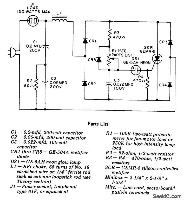
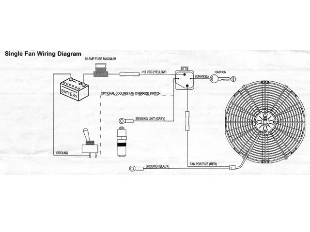
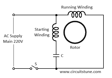
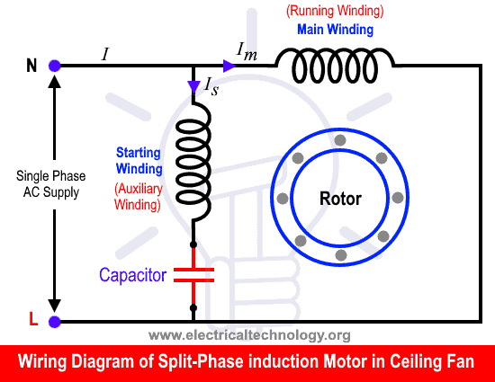
This is a simple illustrated circuit diagram of ceiling fanto be noted that the wiring diagram is for ac 220v single phase line with single phase ceiling fan motor. This fan has an oscillating grill with independent sync motor and timer circuit. As you can see from the diagrams above and below its. Most stand alone adjustable thermostats ie. Suggested electric fan wiring diagrams suggested primary cooling fan single speed onoff using 12 volt switching devices only for primary activation note. So if you want to acquire these incredible shots related to electric fan schematic diagram.
I have a bionaire brand table electric fan. A couple of decades ago it was popular to simply add a switch under the dash to control an electric cooling fan often referred to as an auxiliary fan. With these diagrams below it will take the guess work out. Whether it be a hampton bay hunter or another brand of ceiling fan many fans have the same setup in terms of installation. This might seem intimidating but it does not have to be. The electric motor is a bm 122 decomin brand 3 speed motor.
Here a simple spst switch is used to supply power or not to the fan motor and a regulator is used to controlling the fan speed. There are 6 wires. This was a mediocre way of doing things primarily because the current required to spin the fan was drawn through the switch itself. For example dual thermostat switches or dual relays could be used to control each fan separately. It uses our 40 amp electric relay kit part number 91064044 and electric fan sensor part number 91064013. The supplied diagram is both the most reliable and easiest method ive found.
A question we often get asked is where can i find a wiring schematic or wiring diagram for my ceiling fan. Hayden flex a lite or perma cool brands can provide a 12 volt output when activated. The motor has a 4mu 250volt capacitor.
Gallery of Schematic Diagram Of Electric Fan