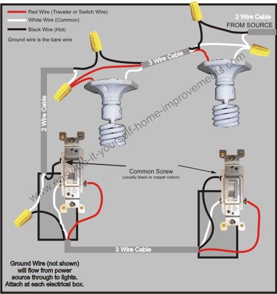
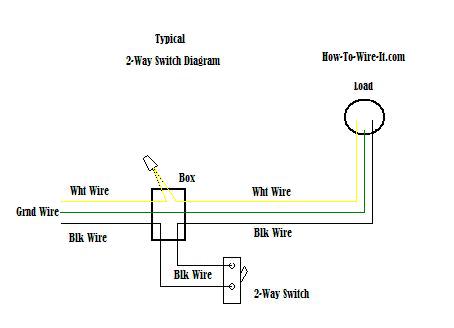
The white wire must be re identified as a hot wire at each switch location. A 3 way switch wiring diagram is a simple drawing showing how to connect the wires to each of the four screws on the 3 way switch.
3 Way Switch Wiring Diagram
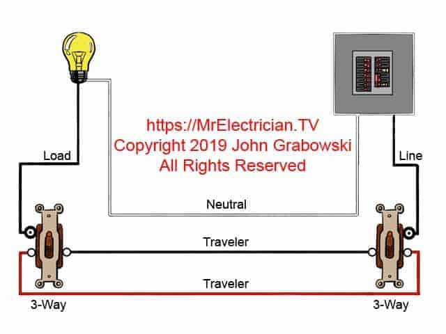
Simple 3 way switch wiring diagram. The fixtures hot wire connects. 3 way switch wire diagram power to light switch in this diagram the incoming hot wire attaches to the first switchs common dark colored terminal. The basic 3 way switch wiring diagram. The two hot wires of three wire cable connect to a pair of brass colored traveler terminals on each switch. 3 way switch 2 3 way wire which has black white and red coated wires and of course a. Take a closer look at a 3 way switch wiring diagram.
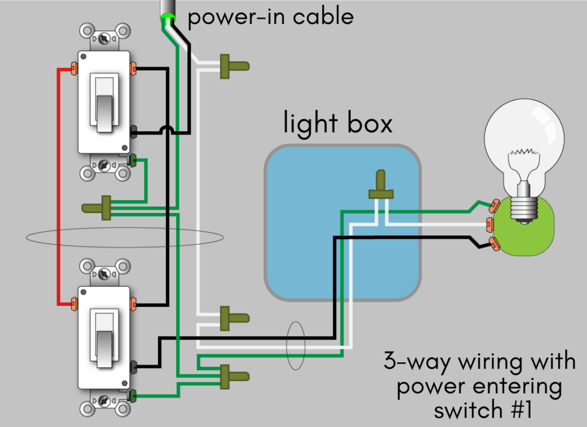
This might seem intimidating but it does not have to be. Three wire cable runs between the switches and 2 wire cable runs to the light. 2 follow 3 way switch diagram. What is the black screw for on a 3 way switch diagram. A 3 wire nm connects the traveler terminals of the first and second 3 way switch together. This wire diagram shows the wiring for source power into the first three way switch then 3 wire cable to the next 3 way light switch and then on to the light or light fixtures.
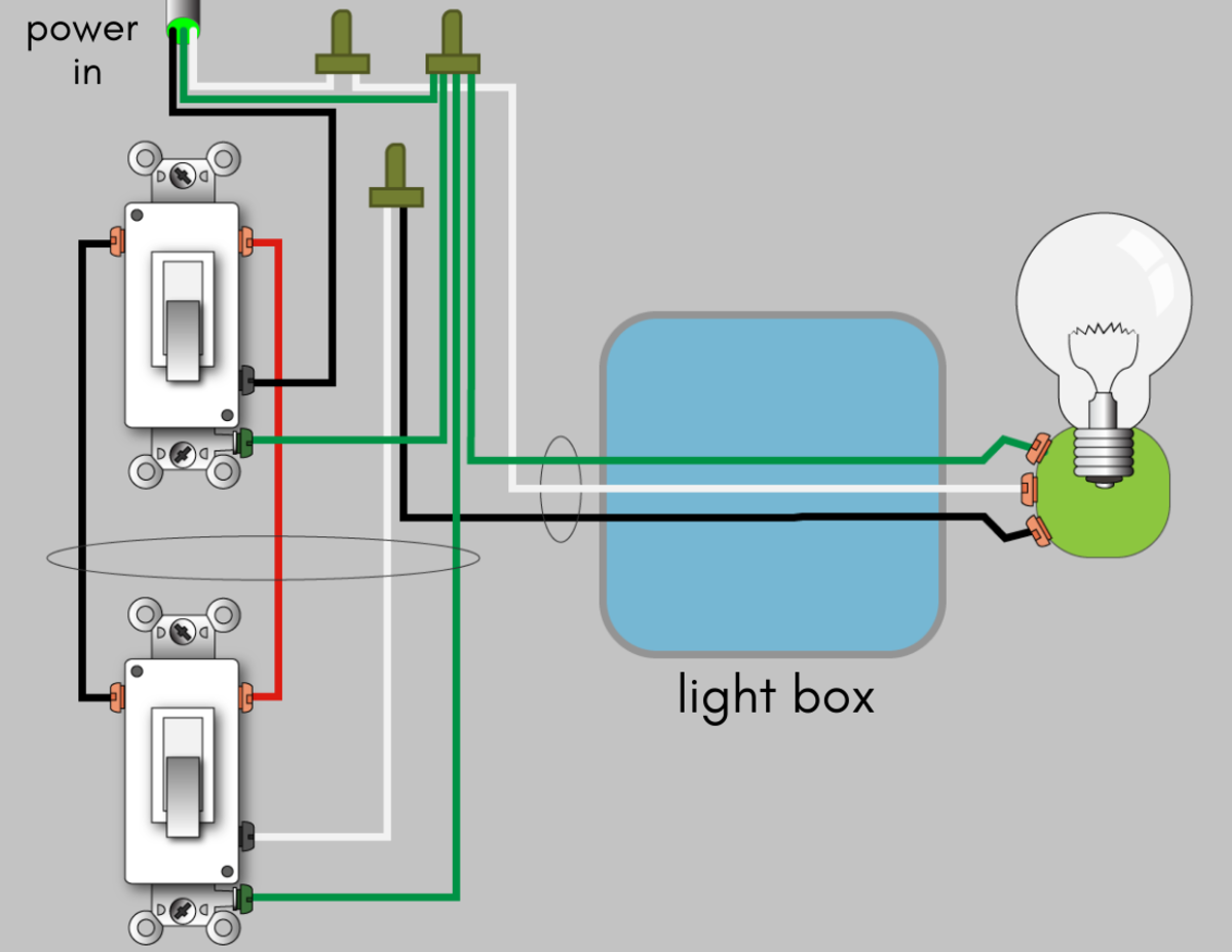
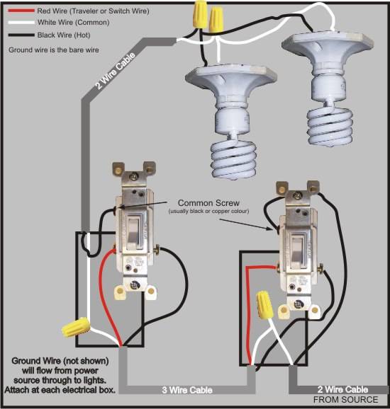
An example of three way switch wiring with the line and load in the same 4 square electrical box. With these diagrams below it will take the guess work out of wiring. 3 way switch wiring diagram with line and load in the same switch box. Typical 3 way switch wiring nm cable in the 1st diagram below a 2 wire nm cable supplies power from the panel to the first switch box. The black and red wires between sw1 and sw2 are connected to the traveler terminals. Simple 3 way switch wiring diagram wiring diagram is a simplified suitable pictorial representation of an electrical circuitit shows the components of the circuit as simplified shapes and the talent and signal contacts amid the devices.
The white wire between switches is not being used as a neutral. The 3 way circuit is a very common system found within most residential installations. Pick the diagram that is most like the scenario you are in and see if you can wire your switch. 1 purchase materials. The black line wire connects to the common terminal of the first 3 way switch. This is the most common and the easiest wiring diagram to follow of any of the wiring diagrams for a 3 way switch circuit.
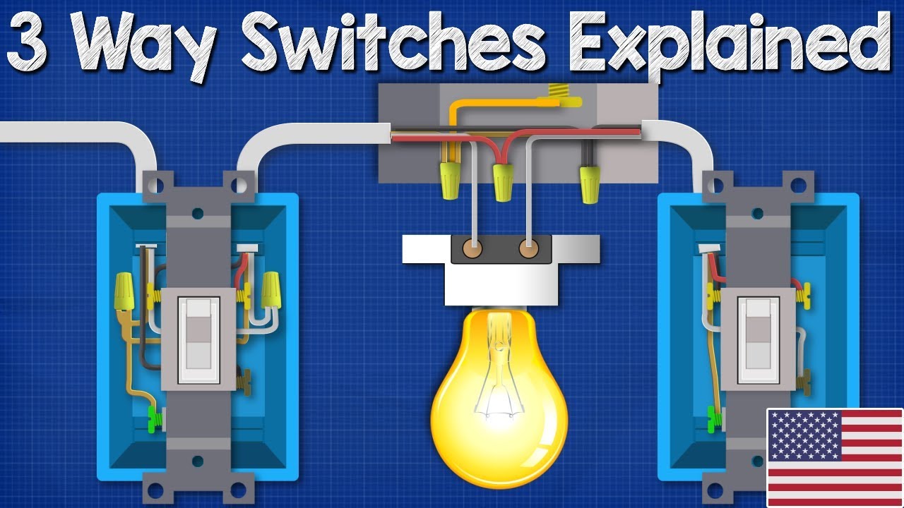
The diagram below is based on the video you watched above. Wiring diagram 3 way switch with light at the end in this diagram the electrical source is at the first switch and the light is located at the end of the circuit. 3 way switch wiring diagram.
Gallery of Simple 3 Way Switch Wiring Diagram