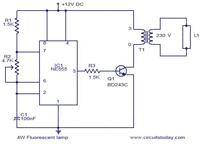
Simple circuit diagram for beginners. Two kinds of transistors are used in this circuit namely transistor number 2n3904 and 2n3906 make an origin frequency circuit.

Simple Headlight Reminders Eeweb Community
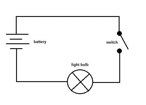
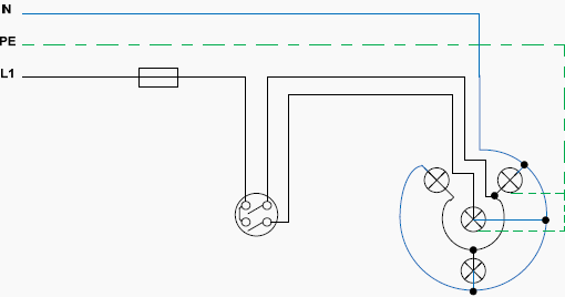
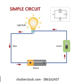
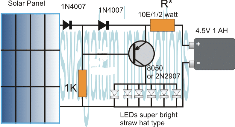
Simple light circuit diagram. The main function of the rectifier is to. One is the neutral wire and the other is the live wire. For a lamp we need two wires. Probably the simplest circuit that can be drawn is one that you may have seen in a school science class. I have quite a collection of solar cells and solar panels most of them salvaged from solar garden lights rescued from the garbage. The positive side of the battery is divided into two directions.
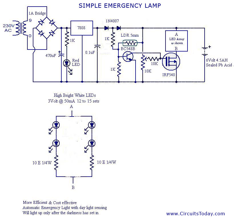
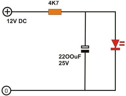
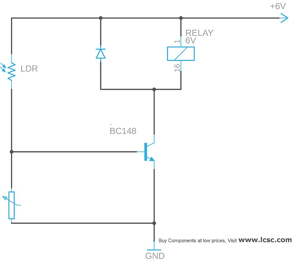
This is a circuit diagram of automatic street light. At first direction there is a resistor of 330 ω and on the other direction 220 ω resistor is connected. In this circuit we will try to connect three 5mm white leds in parallel and light them up using a 12v supply. Circuit diagram for automatic street light. Ldr is a light controlled variable resistor. It is built around a solar lamp controller ic cl0116 ic1 a miniature solar cell a bright white led led1 and a few other components.
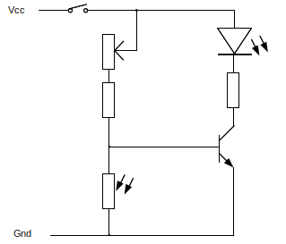
When sunlight falls on the solar cell during daytime the solar cell. Many of them were repaired by me and they range from 15 volt solar cells to 6 volt solar cells and 20 ma to over 100 ma. The first part of a solar circuit is the solar cell or other device for collecting light and making use of it. Light dependent resistor circuit diagram. This is the simple light sensitivity metronome circuit using transistors. Each electronic or electrical component is represented by a symbol as can be seen in this simple circuit diagram.
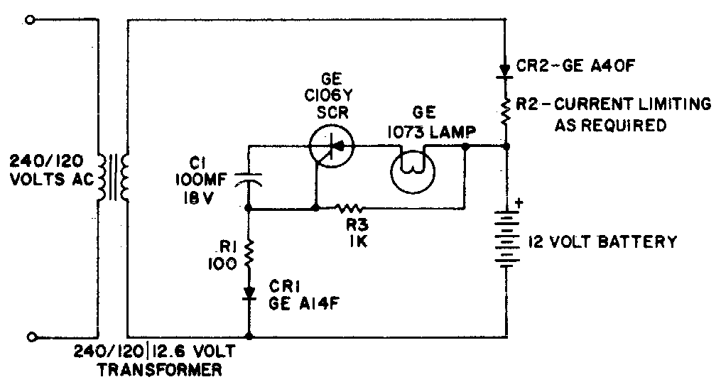
Lines used to connect the symbols represent conductors or wires. Thus the power supply flows through the ldr ground through the variable resistor and resistor as shown in the above light sensor circuit. If the incident light intensity increases then the. Circuit symbols and physical components. A voltage divider made using ldr ldr1 and a potentiometer rv1 b output led d1 in our switching circuit made using a transistor bc547 q1. Battery charging is done by means of a rectifier.
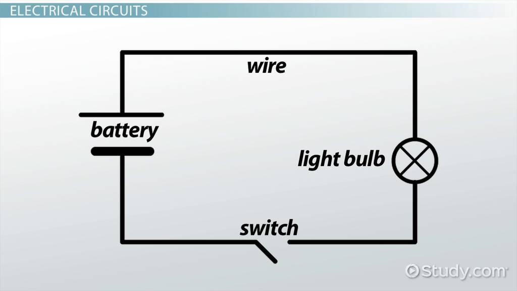
Simple circuit diagram for beginners battery and light bulb circuit. This is due to the resistance offered by the light dependent resistor in the daytime or when. Light detector sensor circuit diagram. Let try to understand this circuit. Sound from a loudspeaker will increase and is down by the frequency in the soundldr is used in this circuit ldr means light dependent resistor also we can call it as a photoresistor or photocell. 10 simple electric circuits with diagrams ac circuit for lamp.
First start form battery. Circuit diagram of solar garden light. The circuit of light detector is very simple and easy to build with very few components. Circuit diagram of the solar garden light is shown in fig. A battery connected to a light bulb as shown below. The circuit diagram for leds in parallel connection is shown in the following image.
Circuit 3 of simple led circuits leds in parallel the final circuit in the simple led circuits tutorial is leds in parallel. This circuit requires only a single ni cd rechargeable battery to light up the white led for more than five hours depending upon the ampere hour ah capacity of the battery. As you can see in the ldr circuit diagram it can be a distinguished as two smaller circuits. In the morning time this sensor has a low resistance around 100ω.
Gallery of Simple Light Circuit Diagram