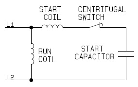
Thus a capacitor start induction run motor produces a better rotating magnetic field than the split phase motors. Split phase single value capacitor electric motor dual voltage type.

3 Phase Motor Wiring Diagram Ke Bmw 7 Mareikekirsch De
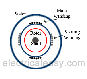
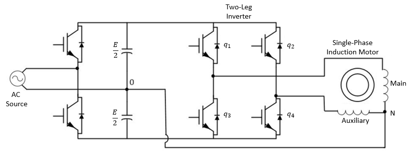
Single phase motor diagram. It is to be. The single phase induction motor is much the same in construction as the three phase motor. The above diagram is a complete method of single phase motor wiring with circuit breaker and contactor. The first component is symbol that indicate electrical element in the circuit. When the stator of a single phase motor is fed with single phase supply it produces alternating flux in the stator winding. The alternating current flowing through stator winding causes induced current in the rotor bars of the squirrel cage rotor according to faradays law of electromagnetic inductionthis induced current in the rotor will also produce alternating flux.
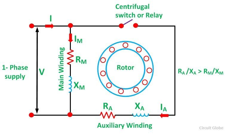
Variety of single phase motor wiring diagram forward reverse. It reveals the components of the circuit as simplified shapes as well as the power and also signal connections in between the tools. It is evident from the phasor diagram that the current through the starter winding is leads the voltage v by a small angle and the current through the main winding im lags the applied voltage. Amazon sells motor start capacitors. This motor has two identical main windings arranged for either series or parallel connections. With the main windings connected in parallel the line voltage is.
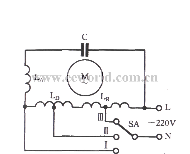
A wiring diagram is a simplified conventional pictorial representation of an electrical circuit. Variety of 240v motor wiring diagram single phase. Figure 17 3 shows a very basic one line diagram of the single phase motor. It reveals the components of the circuit as simplified forms as well as the power as well as signal links in between the tools. Split phase single value capacitor electric motor dual voltage type. Capacitor start capacitor run induction motors are single phase induction motors that have a capacitor in the start winding and in the run winding as shown in figure 12 and 13 wiring diagram.
A circuit is usually composed by many components. There are two things which are going to be present in any single phase motor wiring diagram with capacitor. This type of motor is designed to provide strong starting torque and strong running for applications such as large water pumps. It is important to point out from the phasor diagram that the phase difference between im and is is almost 80 degrees as against 30 degrees in a split phase induction motor. In the above one phase motor wiring i first connect a 2 pole circuit breaker and after that i connect the supply to motor starter and then i do cont actor coil wiring with normally close push button switch and normally open push button switch and in last i do connection between capacitor start motor and contactor. Refer back to this diagram as the operational requirements of the single phase motor are discussed.
Wiring diagram single phase best single phase motor wiring diagram with capacitor start roc grp org ceiling fan wiring diagram with capacitor connection ceiling fan has a capacitor start motor in its inside ac single phase capacitor start motor has two winding one is starting winding and another is. A wiring diagram is a streamlined conventional pictorial depiction of an electric circuit. The other thing that you will get a circuit diagram would be traces.
Gallery of Single Phase Motor Diagram