Thermal contacts tb white m 1 z2 yellow z1 blue u2 black u1 red bridge l1 and l2 if speed controller sc is not required m 1 ln e white brown blue l1 l2 n sc bridge l1 and l2 if speed controller sc is not required diagram dd9 1ø wiring diagrams ln e l1 l2 l3 sc z2 u2 z1 u1 cap. Figure 17 1shows four single phase motor diagrams.

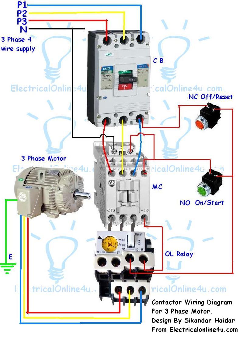
3 Phase Motor Starter Wiring Diagram Pdf Wiring Diagram
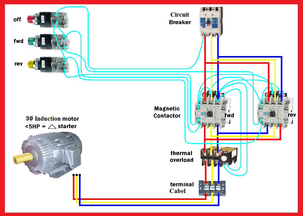
Single phase motor wiring diagram pdf. Assortment of single phase motor wiring diagram forward reverse. Obtaining from point a to direct b. Disconnect all power before servicing. Frequent stopstarts andor changing of the direction of rotation will damage the motors capacitors and winding. Each component ought to be placed and linked to different parts in particular manner. These diagrams are necessary to understand the exact nature and function of the single phase motor.
This type of motor is designed to provide strong starting torque and strong running for applications such as large water pumps. Wiring diagram images detail. For all other single phase wiring diagrams refer to the manufacturers data on the motor. Wiring diagram small packaged heat pump single phase q5rdgq5rdpph2rd 3 ton thru 5 ton notes. Single phase motor starter wiring diagram pdf a novice s overview of circuit diagrams a very first look at a circuit diagram could be complicated yet if you can read a metro map you can review schematics. Not suitable on systems that exceed 150v to ground.
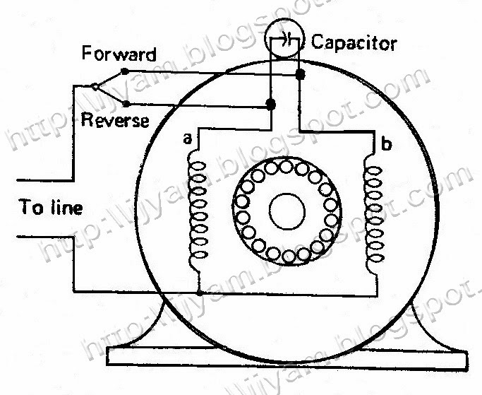
Wiring diagram single phase motors 1empc permanent capacitor motors 1empcc capacitor start capacitor run motors electric motors limited when a change of direction of rotation is required and a change over switch is to be used it will be necessary to reconnect the termination on the terminal block. 2 11 in which vector 1 is 120 degrees in advance of vector 2 and the phase sequence is 1 2 3. 3 phase motor starter diagrams documents 15 pdf drive search and download pdf files for free. Diagrams b and c show a more involved internal wiring system indicat ing two inductors and three terminals. Heating speed electric heat refer to installation instructions for cfm data model orange wire red wire 036 t3 t2 042 t2 t3 048 t3 t2 060 t4 t3. If not the arrangement wont work as it should be.
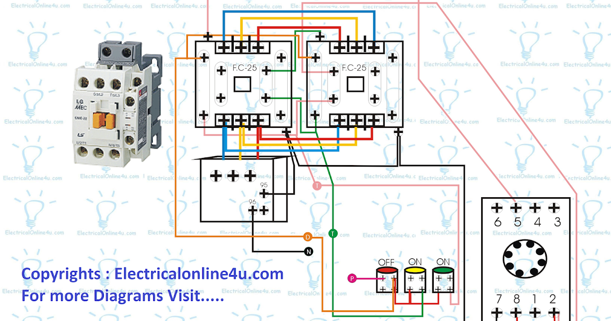
3 phase motor starter diagrams documents 3 phase motor starter diagrams basic wiring for motor contol eaton 3 phase motor a1 a2 95 reset l1 l2 l3 common control separate control 1 3 5 t1 t2 t3 t1 t2 t3 96 97 98 3 2 ìc remote pilot devices 2 wire control 3 wire control start stop 3 2 1 1 3 not for use with auto reset ol relays 2 4 6 m 1 ol 3 phase motor a1 a2 remove wire c when. Click on the image to enlarge and. Refrigeration and manufacturers wiring schematics also use. Single phase motor wiring diagram forward reverse single phase motor reverse and forward connection with capacitor wiring diagram. Terminal markings and internal wiring diagrams single phase and polyphase motors meeting nema standards see fig. Thermal contacts tb white.
See mg 1 221 mg 1 224 direction of rotation. The function is the exact same. It is con cerned only with the overall operation of the electrical distribution system. Single phase motor wiring diagram with capacitor baldor single phase motor wiring diagram with capacitor single phase fan motor wiring diagram with capacitor single phase motor connection diagram with capacitor every electrical arrangement is made up of various unique pieces. Diagram dd6 diagram dd7 m 1 ln e diagram dd8 ln e l1 l2 l3 sc z1 u2 z2 u1 cap. 710837 factory set indoor motor wiring orange wire is coolongheating speed red wire is aux.
For supply connections use copper conductors only. The reconnection must be carried out by qualified electrician. Capacitor start capacitor run induction motors are single phase induction motors that have a capacitor in the start winding and in the run winding as shown in figure 12 and 13 wiring diagram. Literally a circuit is the course that allows power to circulation. Diagram a shows the motor as it will be seen on blueprints and general layouts.
Gallery of Single Phase Motor Wiring Diagram Pdf