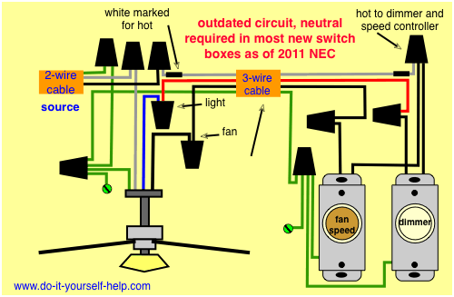
Switched lines and neutral connect to a 3 wire cable that travels to the lightfan outlet box in the ceiling. A wiring diagram is a simplified traditional pictorial depiction of an electrical circuit.

Wiring Diagram For Harbor Breeze 3 Speed Ceiling Fan
Three way fan switch wiring diagram. The black and red wires between sw1 and sw2 are connected to the traveler terminals. The two hot wires of three wire cable connect to a pair of brass colored traveler terminals on each switch. These guidelines will be easy to comprehend and apply. A wiring diagram generally provides information regarding the relative placement as well as setup of tools and terminals on the tools to assist in structure or servicing the tool. It shows what sort of electrical wires are interconnected and can also show where fixtures and components may be. 3 way switch wiring diagram variations ceiling light wiring ceiling fan 3 way switch wiring diagram.
If not the structure will not function as it should be. Wiring diagram 3 way switch with light at the end in this diagram the electrical source is at the first switch and the light is located at the end of the circuit. Wiring diagram 3 way switch ceiling fan and light what is a wiring diagram. Assortment of 3 way fan switch wiring diagram. The common on the second 3 way switch is connected to the hot wires on the fanlight. It really is meant to help all the common person in creating a proper method.
Components of 3 way switch wiring. To wire a 3 way switch circuit that controls both the fan and the light use this diagram. It shows the components of the circuit as streamlined forms and also the power and signal links between the gadgets. A wiring diagram is a straightforward visual representation of the physical connections and physical layout of the electrical system or circuit. As with all 3 way circuits the common on one switch is connected to the hot source wire from the circuit. If you are trying to troubleshoot a 3 way switch operation then you will need to identify the function of each wire.
Three wire cable runs between the switches and 2 wire cable runs to the light. Wires consisting of a line a load a neutral a pair of travelers and two 3 way switches. In this diagram the incoming hot wire attaches to the first switchs common dark colored terminal. Ceiling fan 3 way switch wiring diagram ceiling fan 3 way switch wiring diagram hunter ceiling fan 3 way switch wiring diagram every electric arrangement consists of various diverse components. This 3 way switch wiring diagram shows how to wire the switches and the light when the power is coming to the light switch. The fan control switch usually connects to the black wire and the light kit switch to the red wire of the 3 way cable.
Each component should be set and connected with other parts in specific manner. Wiring diagram arrives with a number of easy to adhere to wiring diagram directions. In this diagram the black wire of the ceiling fan is for the fan and the blue wire is for the light kit. All three way switch and 2 way switch wiring diagrams have the same basic components. Wellborn assortment of wiring diagram 3 way switch ceiling fan and light. 3 way fan switch wiring diagram.
It shows the elements of the circuit as streamlined forms and also the power and also signal connections in between the devices. A wiring diagram is a streamlined conventional photographic depiction of an electrical circuit. November 19 2019 by larry a.
Gallery of Three Way Fan Switch Wiring Diagram