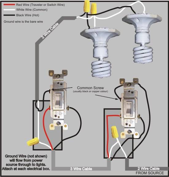
This is a completed circuit. At the outlets each is wired using a pigtail splice to make the hot and neutral connections.

Image Of Wiring Diagram For House Light A Simple Two Way
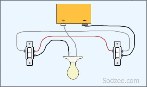
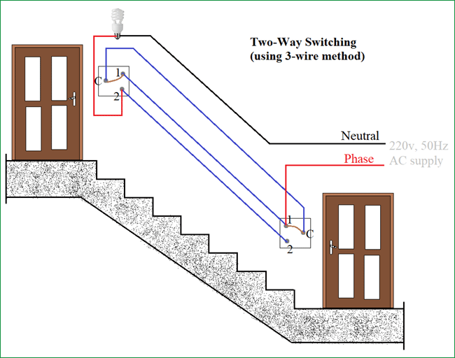
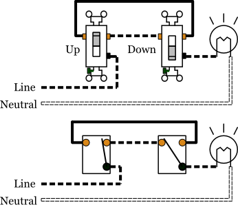
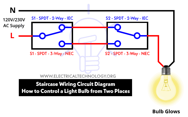
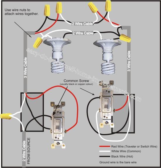
Two way switch wiring diagram two lights. A selection of two way switch lighting circuit diagrams for single and multiple lights with easy to follow circuit guides. According to the schematic diagram of 2 way switch circuit above the common of both the switches are are connected with each other. The electricity flows from the hot wire black through the 2 way switch shown in off position and then to the light and returns through the neutral wire white. 2 way light switch circuit wiring diagrams. It is also a new method to make a 2 way switching connection as it is a little different from the two wire control method. Pin1 of both the switches are connected with the phase or live wire and pin2 of both the switches are connected with the one end of the lamp.
At the light it connects to the neutral terminal. The source for the circuit is at the switch and 2 wire cable runs to each receptacle outlet. The wiring is more complicated than a traditional single pole switch but well explain how to make the connections. Here is our selection of two way switch circuit diagrams. Wiring diagram for multiple switched outlets. Two way switch lighting circuit diagrams.
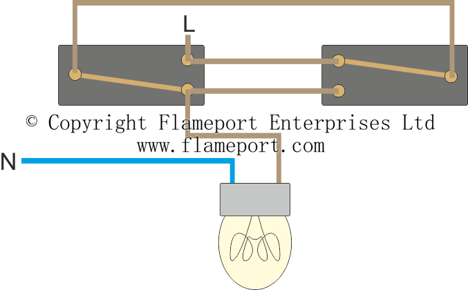
Once youre done youll be able to control a light from two switches. 2 way light switch 3 wire system new harmonised cable colours 2 way switch 3 wire system old cable colours 2 way switch two wire control three way switching. By wiring a 2 way switch the circuit below shows the basic concept of electricity flow to the load. 3 way light switching new cable colours 3 way light switch old cable colours 3 way light switch using a two wire control. This method is commonly used nowadays as it is efficient than the two wire control system. Wiring a 3 way light switch is certainly more.
Lets assume the load you are controlling is a light. Two wire cable runs from the combo to the light fixture and the switch output is connected to the black wire running to the fixture hot terminal. A 2 way switch wiring diagram with power feed from the switch light. The source neutral wire is spliced to the neutral on the receptacle half of the combo device and to the white cable wire running to the light. As you can see in the schematic diagram of 2 way switch circuit below the common of both the switches are short circuited. 2 way switch wiring using three wire control.
This diagram shows the wiring for multiple switched outlets on one switch. The power source comes from the fixture and then connects to the power terminal. This story features diagrams that show how to wire 3 way switches. The electrical symbol indicates where power enters the circuit. 3 way light switching new cable colours 3 way light switch old cable colours 3 way light switch using a two wire control. 2 way light switch 3 wire system new harmonised cable colours 2 way switch 3 wire system old cable colours 2 way switch two wire control three way switching.
You will see that there is a hot wire that is then spliced through a switch and that then goes to the hot terminal of the light.
Gallery of Two Way Switch Wiring Diagram Two Lights