Single phase motor wiring with contactor diagram the above diagram is a complete method of single phase motor wiring with circuit breaker and contactorin the. Ask your own hvac question.
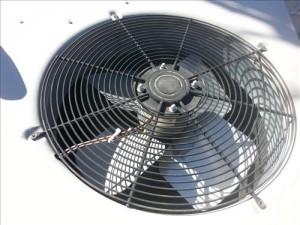
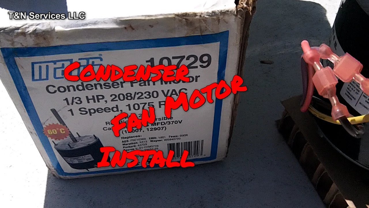
How To Replace A Condenser Fan Motor On An Hvac Refrigeration
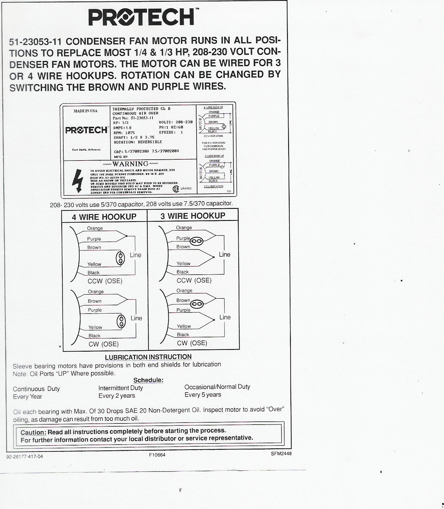
Universal condenser fan motor wiring diagram. This is a quick one on the difference between wiring universal condenser fan motors and why brownwhite is the same wire as white. Share on facebook. Finally this guide is intended to be used as a general overview of common condenser unit wiring schematics. The wiring diagram on the fan will show you how to reverse direction if necessary. Share on twitter. To discover many photos inside condenser fan motor wiring diagram photographs gallery you need to abide by go to.
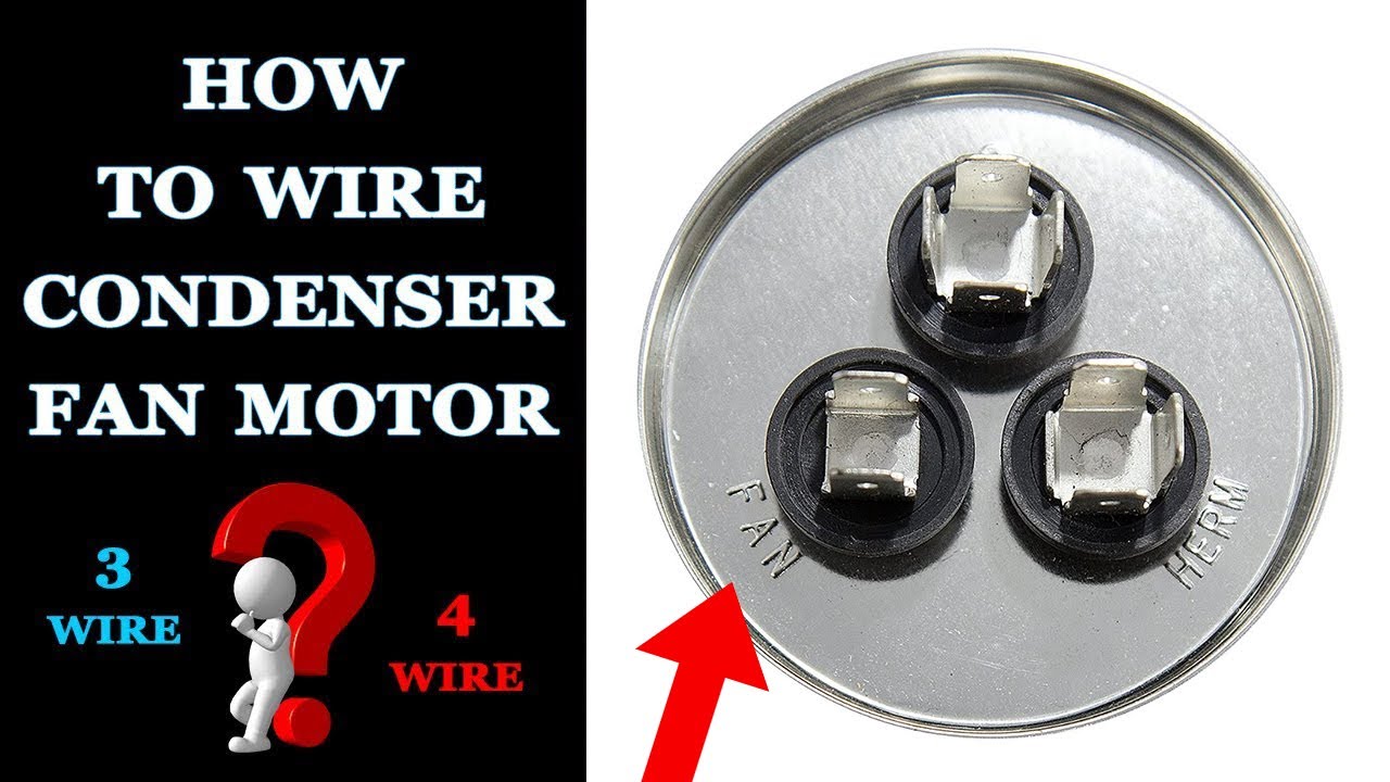
For a visual picture of typical wiring configurations reference the following guide. The problem was the original motor was a four unit and the brown wires went to it 2 prong capacitor and the black to the board and the orange to the contact. Condenser fan motor wiring inspectionnews re. This particular photograph 4 wire condenser fan motor wiring diagram how to wire a universal with condenser fan motor wiring diagram above can be branded together with. Heres the 3 wire method. Ill provide a diagram and explain the wires below.
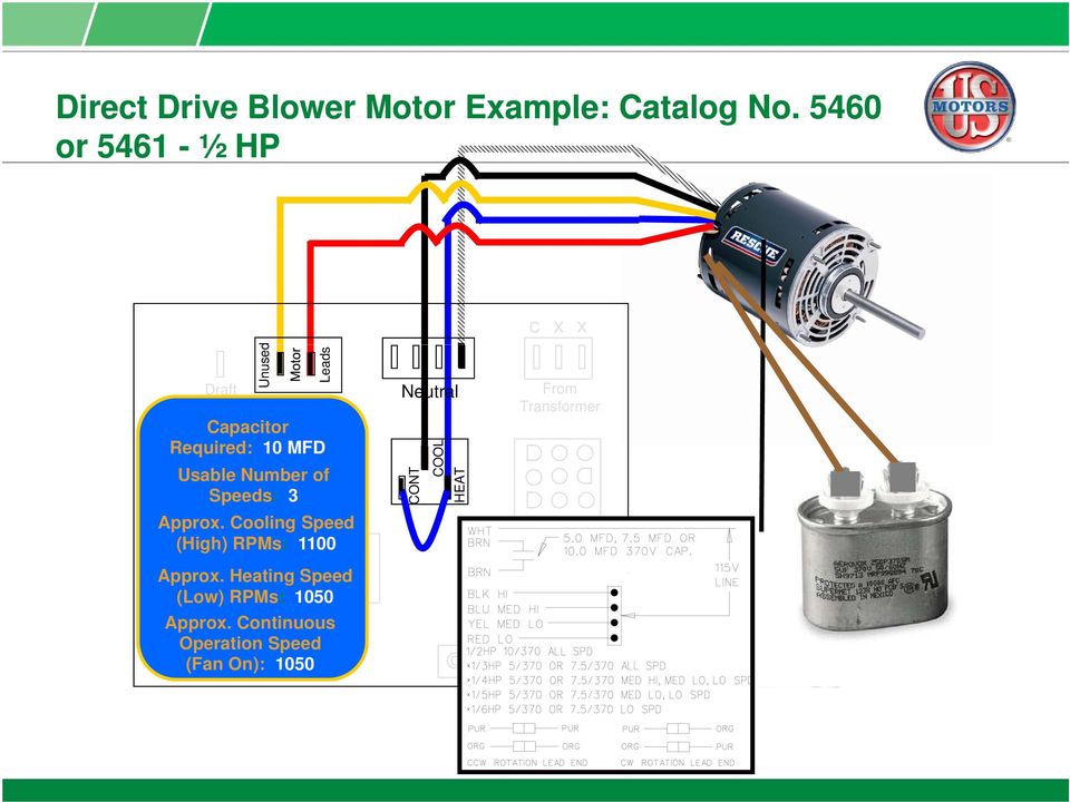
This is ac power and not a dual capacitor so the terminal side does not matter. We replaced the fan motor and capacitor. Hvac condenser fan motor wiring diagram. Refer to the wiring diagram on the particular motor you are using. From the thousands of photographs online concerning condenser fan motor wiring diagram. Its very simple you connect the brown wires.
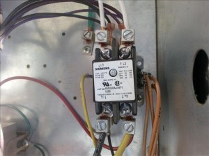
White wire from the condenser fan motor to one side of power on the contactor t1 and jumped to one side of the fan capacitor. Compressor connections to run capacitor as shown in second diagram c common winding goes to t1 on contactor black wire in diagram s start winding goes to herm on contactor blue wire on diagram. Condenser diagram fan. Condenser fan motor wiring originally posted by jerry peck see attached photo arrow is pointing to liquidtight flexible non metallic conduit used to route the fan wiring across under the protective grille and above the fan blades. Submitted simply by tops stars team on june 4 2014. Anything else we should know to help you best.
Hvac condenser motor replacement wiring guide brown contactor fan c herm capacitor original compressor common l1 l2 wire colors may vary l1 l2 208 230 vac s r c new motor new capacitor new capacitor non polarized f terminal is no longer used brown brown white motor contactor fan c herm capacitor original compressor s r c new capacitor only new capacitor non polarized f terminal is no longer used original motor contactor fan c herm capacitor original compressor s. Condenser fan motor wiring diagram. Condenser fan motor thermal overload switch wiring. We strongly recommend referring back to your units manual for proper wiring instructions. How to replace a condenser fan motor with a universal 5 wire to replace the existing three wire with adding a single capacitor to a double capacitor. Some condenser fan motors wire to a circuit board while others use proprietary plugs for their connectors.
The lennox motor said the black goes to the capacitor but in all the diagrams it shows the purple wire goin to the capacitor.
Gallery of Universal Condenser Fan Motor Wiring Diagram