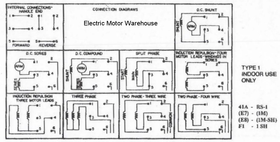
Wiring diagrams standard motors m 3ø wiring diagrams 1ø wiring diagrams m 3 m 3 high speed delta connection low speed star connection w2 or white w2 or white u2 or black u2 or black v2 or orange v2 or orange u1 or red u1 or red v1 or yellow v1 or yellow w1 or blue w1 or blue thermal contacts tb white thermal contacts tb white l1 l1 l2 l2 l3 l3 e e codes. This is weg date.
Reversible Electric Motor Wiring Diagrams H1 Wiring Diagram
Weg motor wiring diagram. Choose the country or region of. Change site language english. A wiring diagram is a simplified traditional photographic representation of an electric circuit. Always use wiring diagram supplied on motor nameplate for motors without thermal protection single voltage single rotation single voltage reversible rotation dual voltage single rotation split phase motor dual voltage reversible rotation capacitor motor single phase wiring diagrams always use wiring diagram supplied on motor nameplate. It reveals the parts of the circuit as simplified shapes and the power and signal links between the gadgets. Collection of single phase motor starter wiring diagram.
Select at least one product to add to your shopping list. Each component ought to be placed and linked to different parts in particular manner. Iom installation operation and maintenance manual of electric motors date. Severe duty is standard with weg w22 motors date. English spanish brazilian portuguese size. Weg motor scan installation and operation manual date.
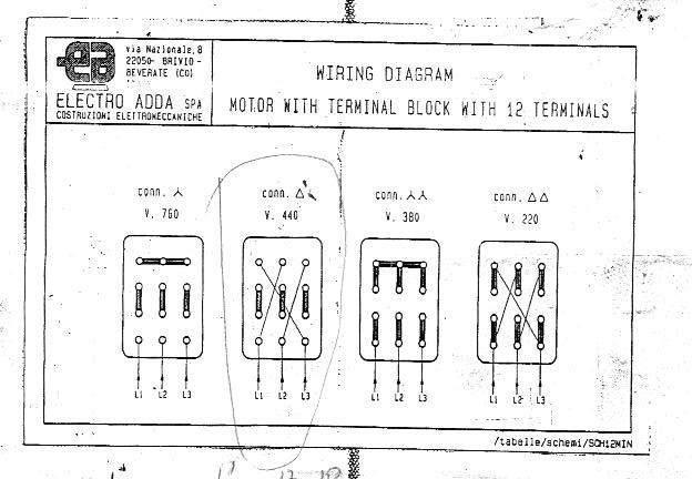
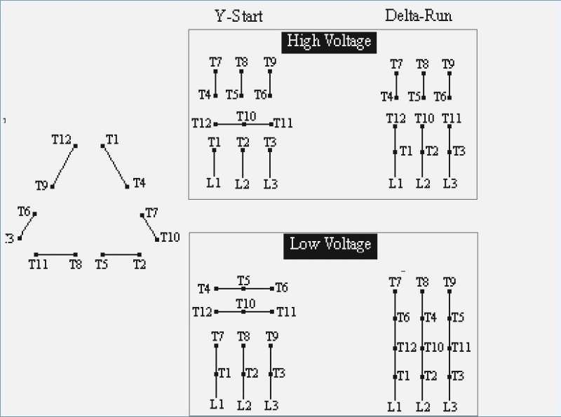
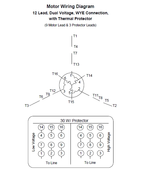
Weg in numbers. Weg electric motor wiring diagram wiring diagram is a simplified within acceptable limits pictorial representation of an electrical circuit. Single phase motor wiring diagram with capacitor baldor single phase motor wiring diagram with capacitor single phase fan motor wiring diagram with capacitor single phase motor connection diagram with capacitor every electrical arrangement is made up of various unique pieces. Russian english bulgarian german romanian spanish brazilian portuguese size. Typical wiring diagrams always use wiring diagram supplied on motor nameplate connection diagrams co leads part winding weg three phase motors volts 12 lead part winding 12 10 11 12 3 l1 l2 12 10 11 64 5 78 9 12 l1 l2 12 10 11 64 5 l1 l2 starting type volts across line starting type volts soft. W2 cj2 ui vi wi w2 cj2 ui vi wi a cow voltage y high voltage z t4 til t12 10 til t4 t5 ali l2 t12 ti blu t2 wht t3org t4 yel t5 blk t6 gry t7 pnk t8.
Sugar ethanol. And upwards diagram dd5 two speed motors for all other single phase wiring diagrams refer to. Frequently asked questions faq violation of the code of ethics news. It shows the components of the circuit as simplified shapes and the capability and signal connections along with the devices. 6655 sugarloaf parkway duluth ga 30097 ga usa. Installation operation and maintenance manual of electric motors 50033244 date.
If not the arrangement wont work as it should be. You need to select at least 1 product to add in your comparison list. Select at least one list to add to your products.
Gallery of Weg Motor Wiring Diagram