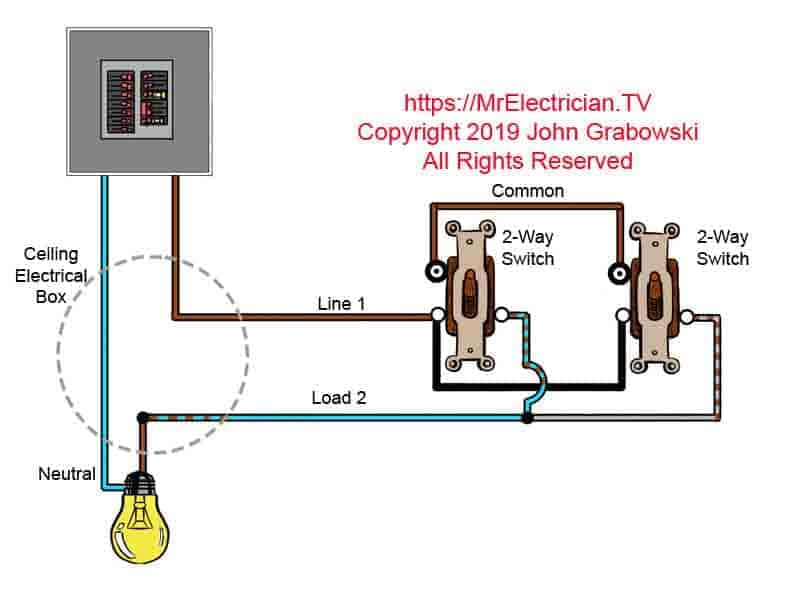
The black and red wires between sw1 and sw2 are connected to the traveler terminals. Diy mower will not crank safety switch diagnosis and my cub cadet rzt would not crank safety switch diagnosis and repair cub cadet rtz ztr how safety switches work on your cub cadet key switch diagram imageresizertool cub cadet key switch diagram furthermore pto switch wiring diagram further manual pto as well as 36 volt ez go golf cart wiring diagram to her with.
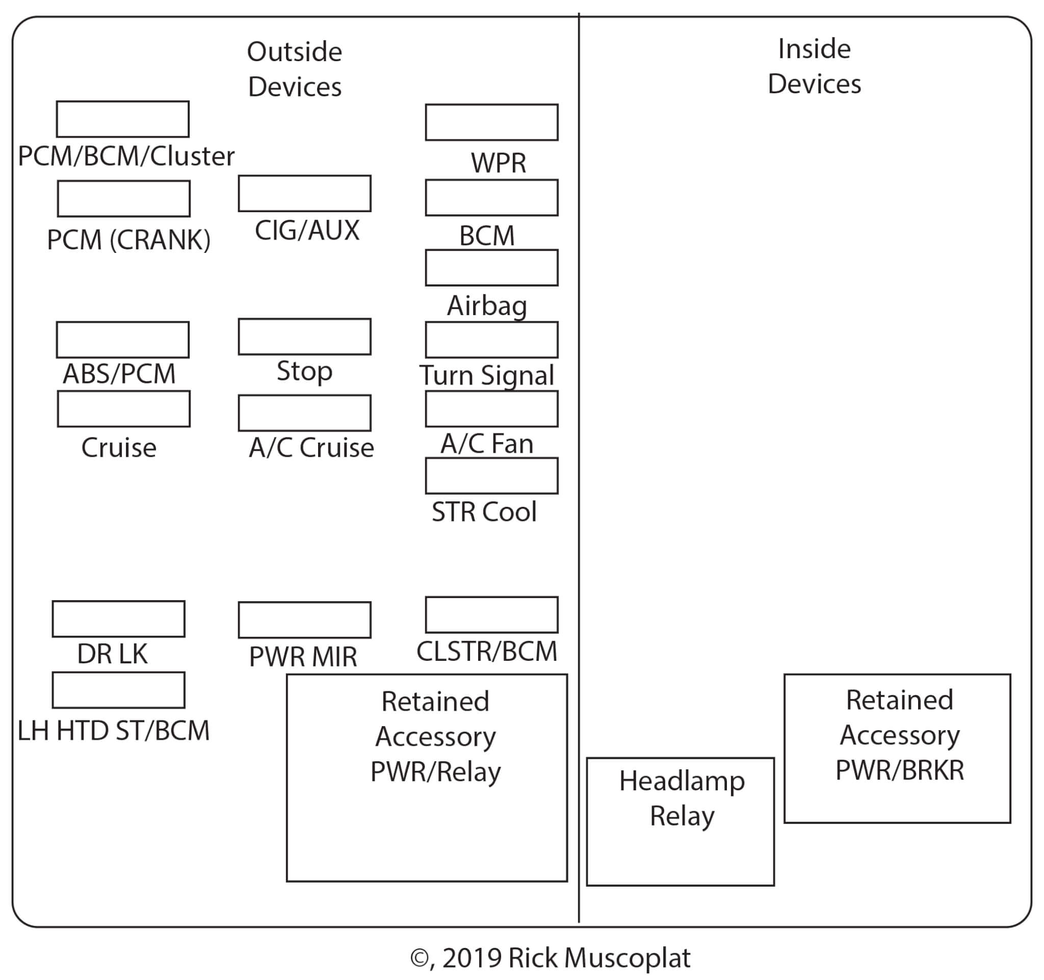
2004 Chevrolet Impala Fuse Diagram Ricks Free Auto Repair
Where is the switch located on this diagram. This allows computers to have dedicated bandwidth on point to point connections to the network and also to run in full duplex mode. Where is the resistor located on this diagram. In either case applying electrical current to the contacts will change their state. Archive yachting and boating world forumsest ignition shift. In the diagram if a lightbulb is placed at d and b is closed as shown what will happen. When a relay contact is open the relay is not energized.
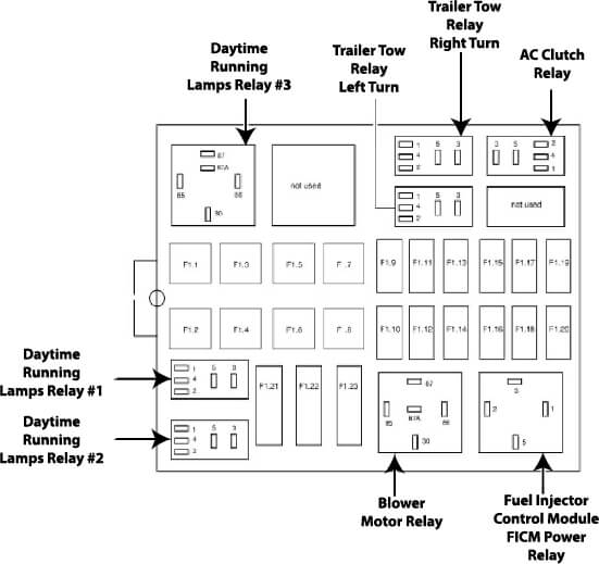
The fuse box is located behind the storage compartment to the left of the steering wheel. The lightbulb will be off. Micro segmentation each device is located on a dedicated switch port. Front blower motor relay front air control. Fuse box 2 diagram. Where is the switch located on this diagram.
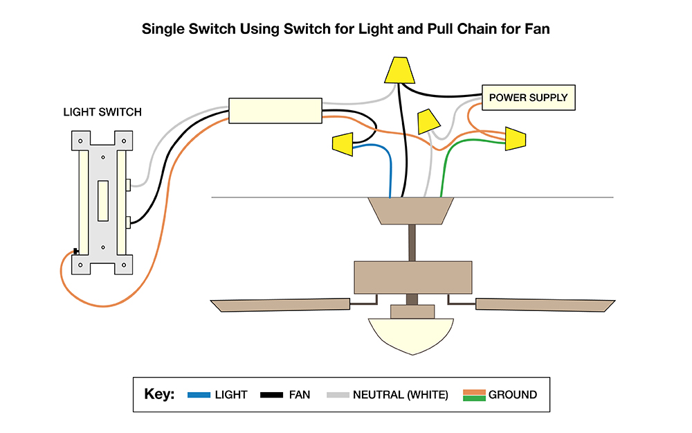
Body control module bcm. In the extreme case ie. Assignment of fuses in the instrument panel ampere rating description. Three wire cable runs between the switches and 2 wire cable runs to the light. The lightbulb will be on. Pedal adjusting control unit stop lamp switch.
In this diagram the electrical source is at the first switch and the light is located at the end of the circuit. Fusible link block main fuses instrument panel fuse box. The fuse box is located behind the cover to the left of the steering wheel. When a relay contact is closed there is a closed contact when the relay is not energized. Cub cadet safety switch diagram. Here we look at relay switch pin diagram and the different kinds of relay switches.
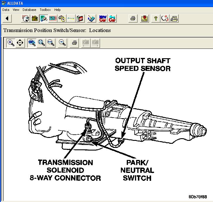
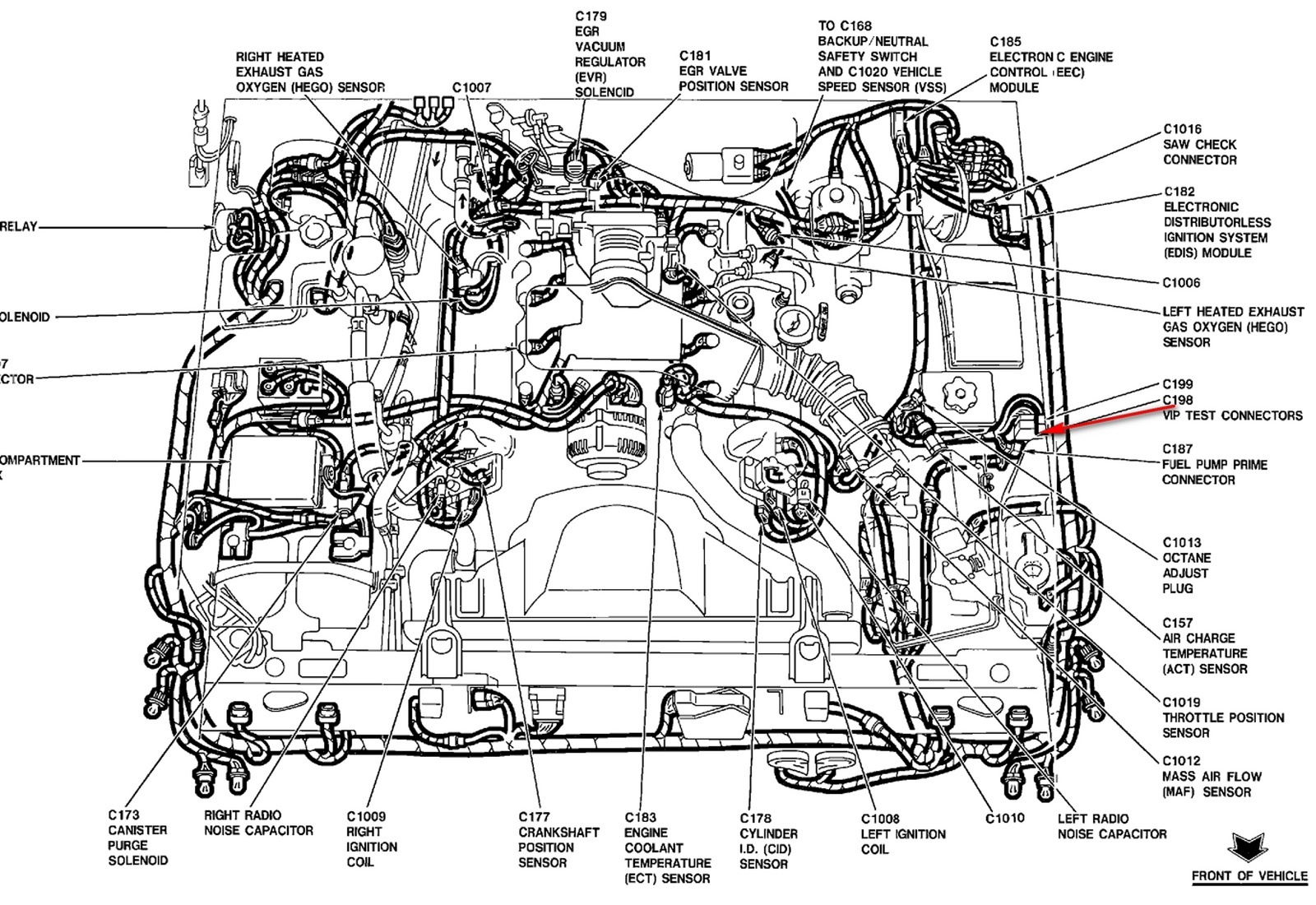
Air bag diagnosis sensor unit. Relays are generally used to switch smaller currents in a control circuit and do not. Some neutral safety switches are nonadjustable. A neutral safety switch allows current to pass from the starter switch to the starter when the lever is placed in the p or n position. A network switch also called switching hub bridging hub officially mac bridge is. Assignment of the fuses and relays in the instrument panel amp description.
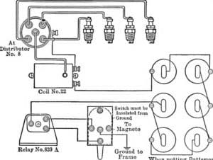
Mercury outboard ignition switch wiring diagram. The lightbulb will be hotter than normal. Typical location of a neutral safety switch on a transaxle. Universal ignition switch wiring diagram page 1 iboats re universal ignition switch wiring diagram you are probably looking at ignition switches for an i o outboard switches require more and different ignition coil troubleshooting tips for mercury mariner mercury mariner ignition coil diagrams coil packs and repair manuals troubleshooting tips bad ignition coil symptoms ignition coil replacement. In contrast to an ethernet hub there is a separate collision domain on each of the switch ports. Trnsmission control module tcm closed throttle position switch.
If these prevent starting in the p or n position and the gear selector linkage is correctly adjusted they should be replaced. Where is the switch located on this diagram. Answerb in the diagram. Reprinted with permission of ford motor company. The lightbulb will short out. Mercruiser shift interrupter switch diagram thanks for visiting our site this is images about mercruiser shift interrupter switch diagram posted by maria rodriquez in diagram category on nov 15 you can also find other images like wiring diagram sensor location fuel pump location starter location control module location parts diagram replacement parts electrical diagram repairmercruiser forward to neutral cuts out.
Body control module bcm auto anti. Passenger compartment fuse box. Fuse box 1 diagram. Relays switches are used to open and close circuits electromechanically or electronically. Full duplex mode has only one transmitter and one receiver per collision domain.
Gallery of Where Is The Switch Located On This Diagram