It shows the elements of the circuit as streamlined shapes as well as the power and also signal connections in between the gadgets. This device can be used in place of any of the 3 way switches in these circuits as well as to dim the lights in a.
3 Way Dimmer Problem Terry Love Plumbing Advice Amp Remodel
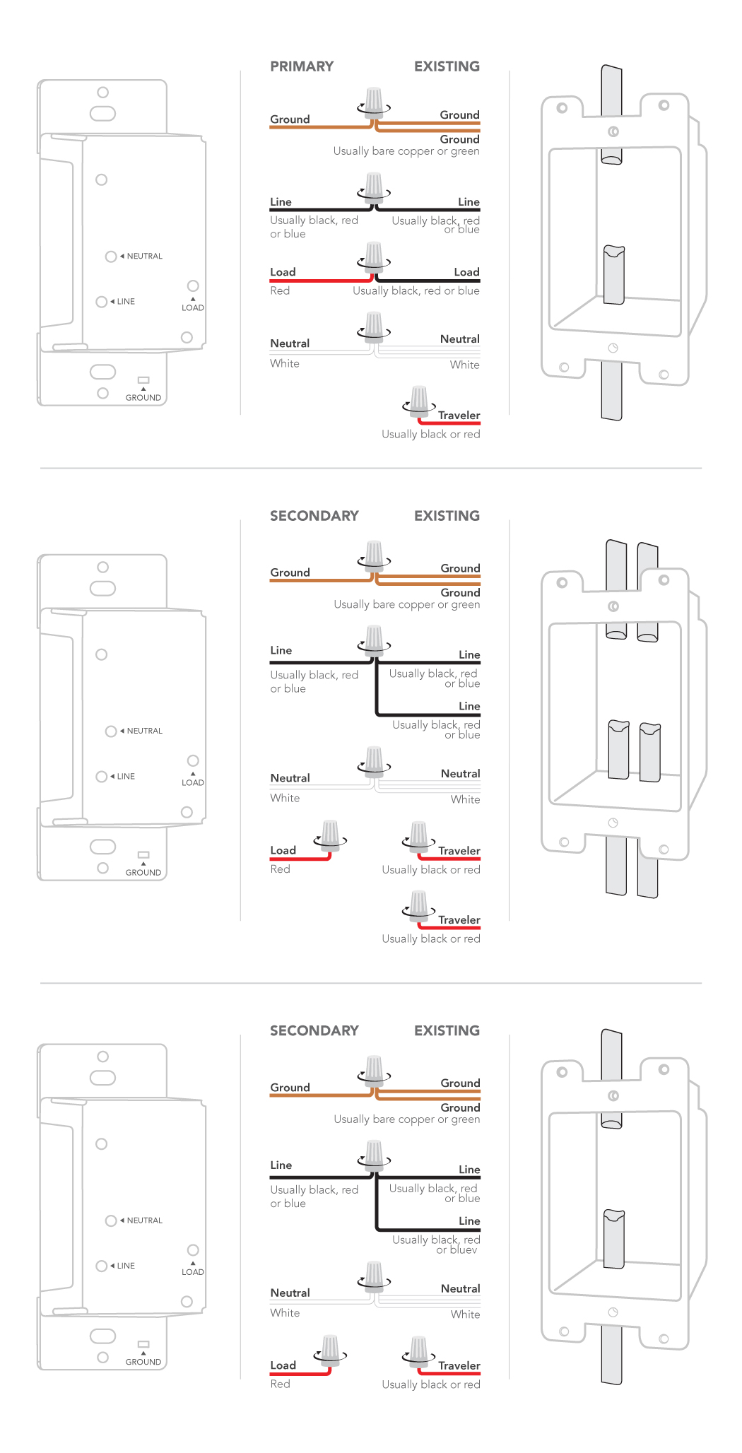
4 way dimmer wiring diagram. This 4 way switch diagram 2 shows the power source starting at the fixture. The diagram shows how the wiring works. The white wire becomes the energized switch leg as indicated by using black or red electrical tape. The w y and g terminals should be pretty straight forward on most all types of thermostats. 4 way switch wiring diagrams this 4 way switch diagram 1 shows the power source starting at the left 3 way switch. The following 3 diagrams show the wiring for a specially made dimmer that can be used in these circuits in place of either of the the 3 way switches or both.
Lutron 4 way dimmer wiring diagram collection variety of lutron 4 way dimmer wiring diagram. How to wire a 4 way. The key to 4 way switch wiring. The white wire of the cable going to the switch is attached to the black line in the fixture box using a wirenut. Just take a look at the picture below the diagram. More 4 way switch wiring diagrams four way switch wiring schematic.
Whenever the white wire in a cable is not being. 4 way dimmer switch wiring diagram this is the wiring for a dimmer in a 4 way circuit. Three wire cable runs between all the switches and 2 wire cable runs to the light. Call the lutron hotline 800 523 9466 to ordercall lutron customer service 610 282 3800 neutral. 4 way switch wiring diagram with dimmer wiring diagram is a simplified tolerable pictorial representation of an electrical circuit. To make this circuit work a 3 way dimmer can be used in place of one or both of the standard 3 way switches.
More about wiring a 4way switch. Wiring diagram 4 3 way wiring model dvelv 303p ca 3ps wiring diagram 5 3 way used as single pole model dvelv 303p wiring diagrams wiring diagram 1 single pole wiring model dv 600p dv 10p dvlv 600p dvlv 10p ca 1psh wiring diagram 2 single pole wiring of 3 way control model dvfsq f dvlv 103p dvlv 603p dv 103p dv 603p wiring diagram 3 single pole wiring model dvelv 300p have questions. However your connections may seem a little different on the thermostat itself. The red wire or 24 vac power lead is connected straight to the rc 4 terminals. After the lighting level has been set on one dimmer the other switch will turn the lights off and on at that level. 3 way dimmer switch wiring diagrams.
Installing dimmers for 3 way and 4 way switches i have a four way switch set up like your diagram shows and it works great. A wiring diagram is a basic graph of the physical connections as well as physical format of an electric system or circuit. Some thermostat units have a dedicated r terminal and it jumpers to the rc rh or 4 terminals internally. A wiring diagram is a simplified traditional pictorial depiction of an electric circuit. Use electrical wiring layouts to aid in building or making the. When and also the best ways to use a wiring diagram.
This arrangement allows for lowering the lights in a 3 way circuit. It shows the components of the circuit as simplified shapes and the aptitude and signal friends amongst the devices. Lutron 4 way dimmer wiring diagram luxury lutron maestro dimmer exactly what is a wiring diagram. The electrical switch box that contains the line and load wires may need to be bigger than the other switch boxes especially if there are other wires going into the switch box. It reveals exactly how the electrical wires are interconnected as well as can likewise reveal where components and parts might be attached to the system. As long as the switch is on the other switches in the circuit work and i can dim the lights.
However if i turn the dimmer. Below is another method for wiring 4 way switches. The dimmer switch now acts like a master switch.
Gallery of 4 Way Dimmer Wiring Diagram