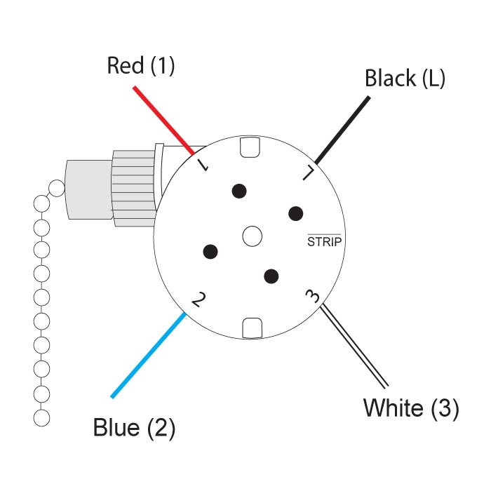
February 28 2019 by larry a. Connect the red wire to the screw in switch 2.
Zing Ear Ze 208s E89885 3 Speed 4 Wire Pull Chain Ceiling Fan
4 wire fan switch wiring diagram. 21 posts related to hunter 4 wire ceiling fan switch wiring diagram. Collection of 4 wire ceiling fan switch wiring diagram. Wiring diagram for bathroom fan 2019 heller exhaust fan wiring. It shows the way the electrical wires are interconnected which enable it to also show where fixtures and components could. Connect the blue wire to the red wire. Simple wiring diagram for bathroom fan with timer.
The complete guide to help you decide what pull chain ceiling fan switch is right for you category number 1 3 speed 4 hole ceiling fan switch with black wire in terminal l and labeled l 1 2 3 counterclockwise zing ear ze 268s1 rating. A wiring diagram is an easy visual representation with the physical connections and physical layout associated with an electrical system or circuit. Ceiling fan 4 wire switch wiring diagram. Hunter 4 wire ceiling fan switch wiring diagram. Hunter ceiling fan wiring diagram switch. A wiring diagram is a streamlined standard pictorial depiction of an electrical circuit.
4 wire ceiling fan switch wiring diagram what is a wiring diagram. 4 wire ceiling fan switch wiring diagram awesome 4 wire 3 speed 4 wire fan switch wiring diagram collection 3 speed ceiling fan switch siphro org ceilingfanswitch zing ear ze 268s6 switch 3 speed 4 wire 3 speed fan switch 4 wires diagram coil thermostat how does 3 speed 4 wire pull chain fan switch wiring ceiling three. Bathroom fan with timer wiring diagram collections of bathroom fan with timer wiring diagram collection. Connect black fan wire to the black ceiling wire. The old zing ear switch i am replacing is a shine top ls 102 6a125vac 3a250vac e218558. 6a 125vac 3a 250vac.
I purchased a 3 speed 4 wire fan switch model number ze 268s6 and i am trying to figure out where to insert the color wires. My fan has four speeds off slow medium and fast. 4 wire ceiling fan switch wiring diagram. Wiring diagram for bathroom fan simple wiring bathroom fan light. Connect the black wire to the screw located in swith 1. Split the incoming hot wire into a y and connect it to a terminal on each switch.
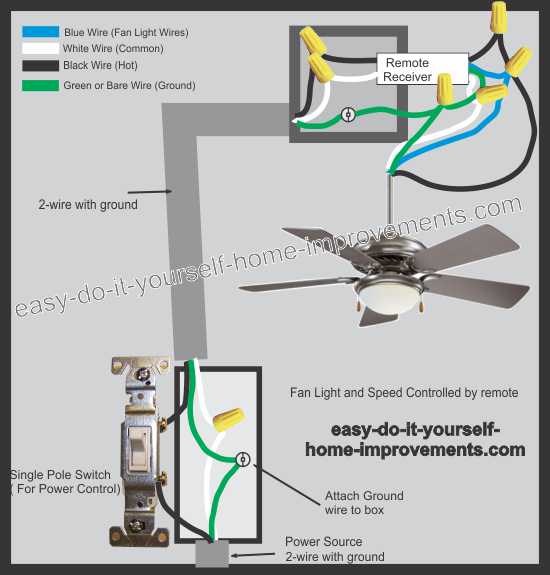
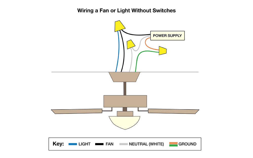
September 12 2019 by admin. 5 wire ceiling fan switch wiring diagram. In the switch box. Line voltage enters the switch outlet box and the line wire connects to each switch. Connect white wires together. Switched lines and neutral connect to a 3 wire cable that travels to the lightfan outlet box in the ceilingthe fan control switch usually connects to the black wire and the light kit switch to the red wire of the 3 way cablein this diagram the black wire of the ceiling fan is for the fan and the blue wire.
It reveals the elements of the circuit as simplified shapes and the power and signal connections between the tools.
Gallery of 4 Wire Fan Switch Wiring Diagram