Relay test 1 set meter to 200 ohms test for resistance between 85 and 86 circuit with coil acceptable range 50 to 120 ohms example 70 ohms is good below 50 or above 120 ohms relays is bad. No car wiring can be complete without these.

2000 Honda Prelude Srs Relay Electrical Problem 2000 Honda
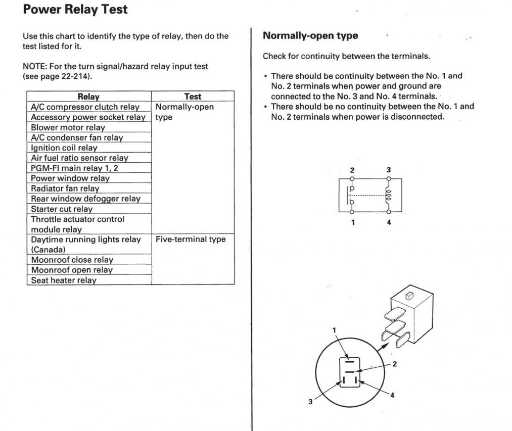
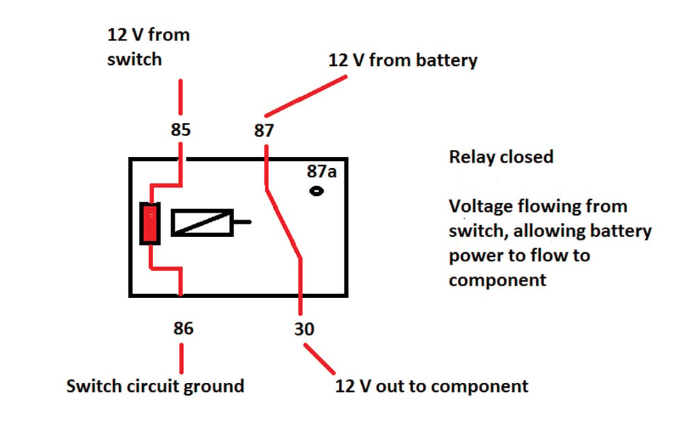
Test 4 pin relay. In this article we will show what resistance readings you should get when you measure various points of a relay. Since the common pin is determined thus another one remaining pin in the connected pins detected in step 3 must be the normally closed nc pin. Switch circuit that controls accessory item ie starter motor 30 power in hot 87 power out. Determine the common pin of the relay when the relay is activated. Como diagnosticar un relevador duration. The simplest way of finding this is to use a multimeter with an ohmmeter setting and then measuring the resistance values by checking its terminals.
How to test a relay. From ignition key 85 ground. In this article we will see what resistance readings are required to declare that the relay you are using is the good or defective. 7 steps with pictures. 2 will connect to the control circuit and 2 will connect to the high power load. Relays are the integral component of any car wiring.
A 4 terminal relay is used so a low. Then with the multimeter set to continuity test mode check which pin is now connected to the normally open no pin in this moment. I will show you how to test a 3 4 and 5 pin relay. How to test a four terminal relay. How to test a 3 4 or 5 pin relay with or without a diagram duration. Now all the pins of relay have been determined as in figure 9 below.
7 steps with pictures. How to test a four terminal relay. Relays are used to bypass signal wire and directly supply current from battery thus your car wiring remains safe from heating up and burning due to the load of heavy components. In this post we are going to learn how to test a relay with a multimeter step by step. To test a relay to see whether it is good or defective the simplest way to do would be to use a multimeter set to the ohmmeter setting and measure various resistance values of the relay. How to test a 4 pin relay.
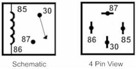
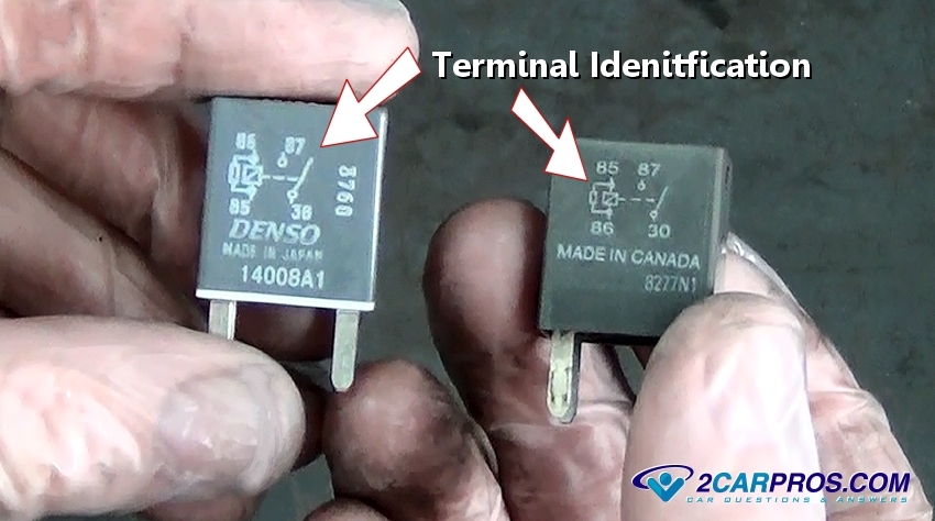
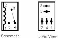
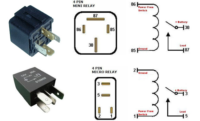
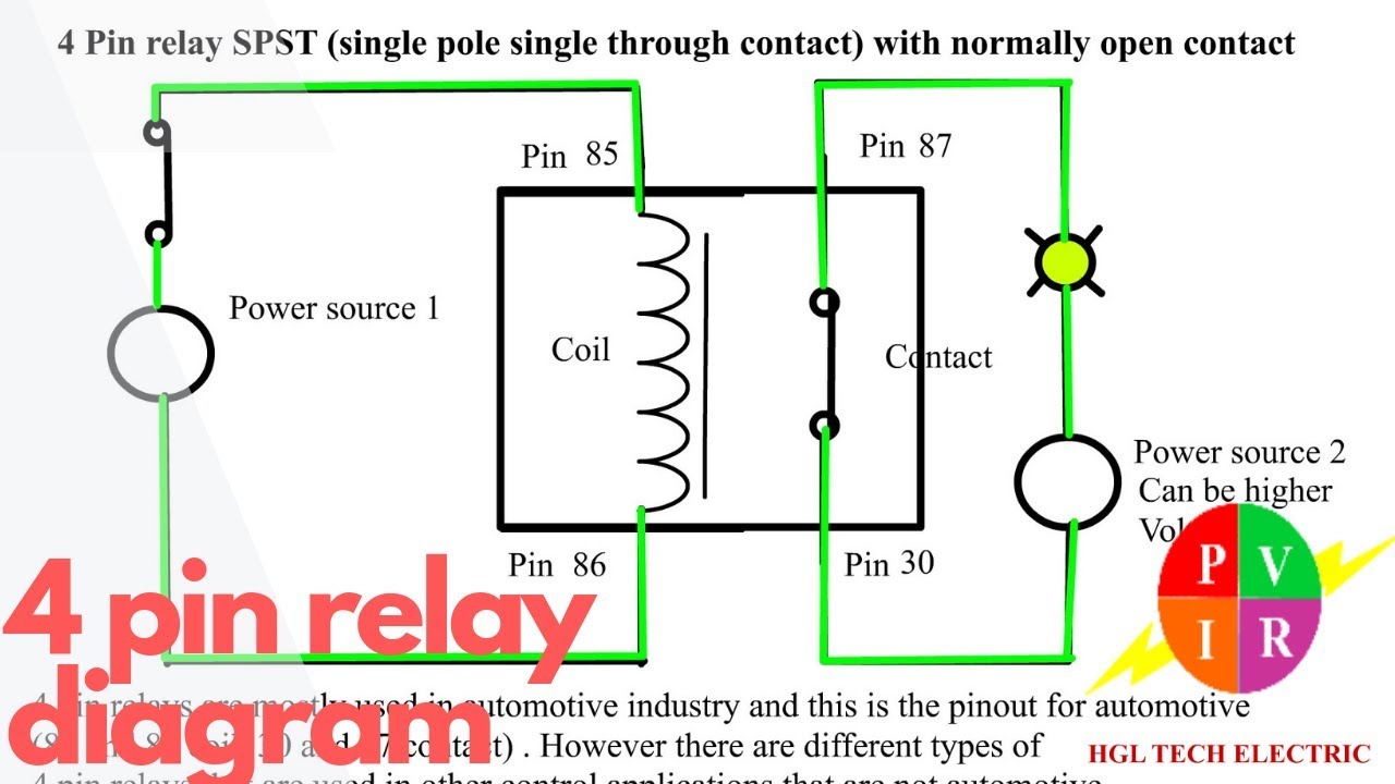
Relay test 2 listen for a. The relay will have 4 pins. For example a low power circuit in a car that commands the high. Test the coil terminals of the relay with an ohmmeter. 4 pin relay 4 pin relays use 2 pins 85 86 to control the coil and 2 pins 30 87 which switch power on a single circuit. Denso relay 4 pin wiring diagram.
How to test a relay with a multimeter. By finding the resistance values we will be able to test a relay to find whether its good or bad. The international standards organization iso defines this type of relay as 1 inch 25 cm square 254 mm square. How to test a four terminal relay. The main reason for testing a relay is to find whether it is a good or defective one. A 4 terminal relay is used so a low power circuit may engage a high power circuit without risk of damage to the low power control circuit.
Ratchets and wrenches 1039300 views. How to test a four terminal relay. That pin would be the common pin. We will start with. Denso parts are often used in japanese assembled cars including cars manufactured by renowned brands like toyota honda mitsubishi suzuki mazda daihatsu and several others. Identify the relay as an iso mini type.
Control circuit shows resistance 50 to 120 ohms 86 power in example.
Gallery of Test 4 Pin Relay