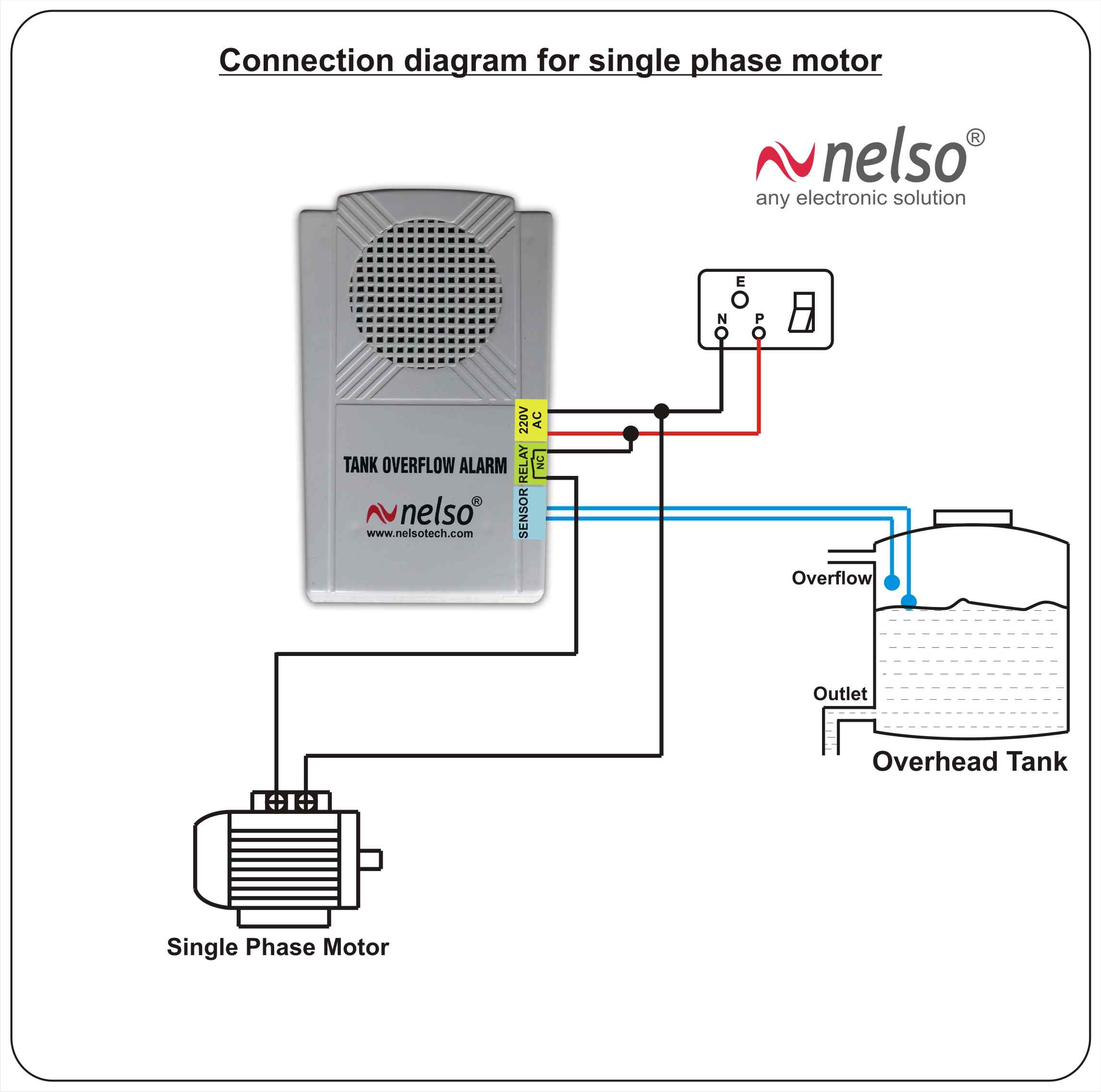
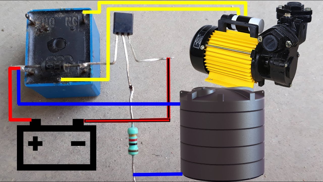
The motor gets automatically switched on when water in the overhead tank oht falls below the lower limit. The wiring connection of submersible pump control box is very simple.

Automatic Water Pump Controller Circuit With Indicator
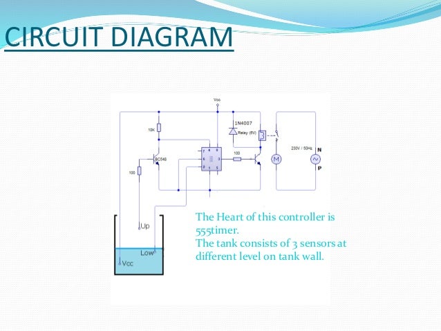
Automatic pump controller circuit diagram. Working of this circuit is almost similar to a bi stable mutlivibrator. Working of automatic water tank level controller we know the property of 555. Heres a automatic water pump controller circuit that controls the water pump motor. Hello readers we frequently add new circuit diagrams so do not forget to come back often. But waste a lot of electricity. This project uses a magnetic float sensor in it.
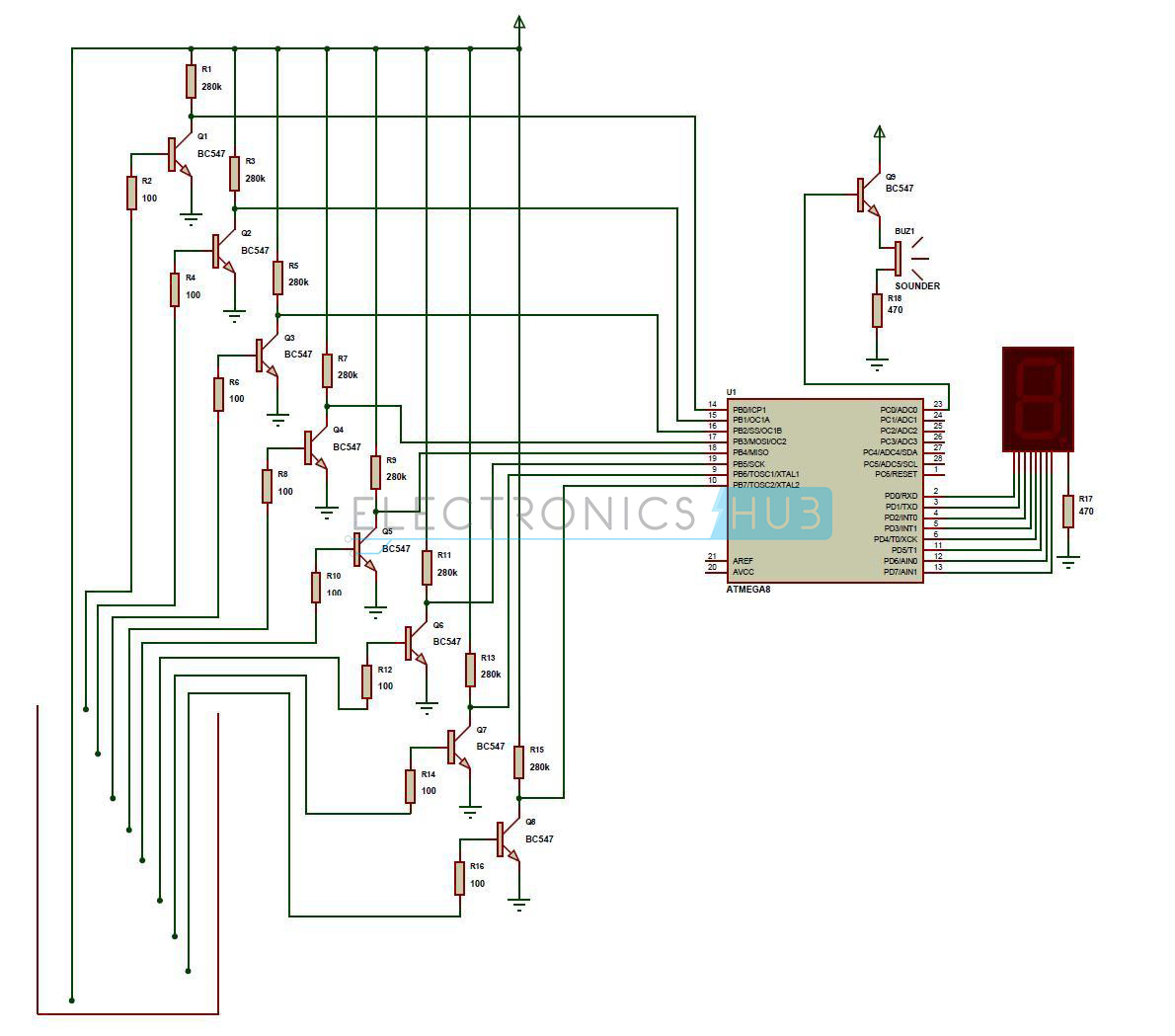
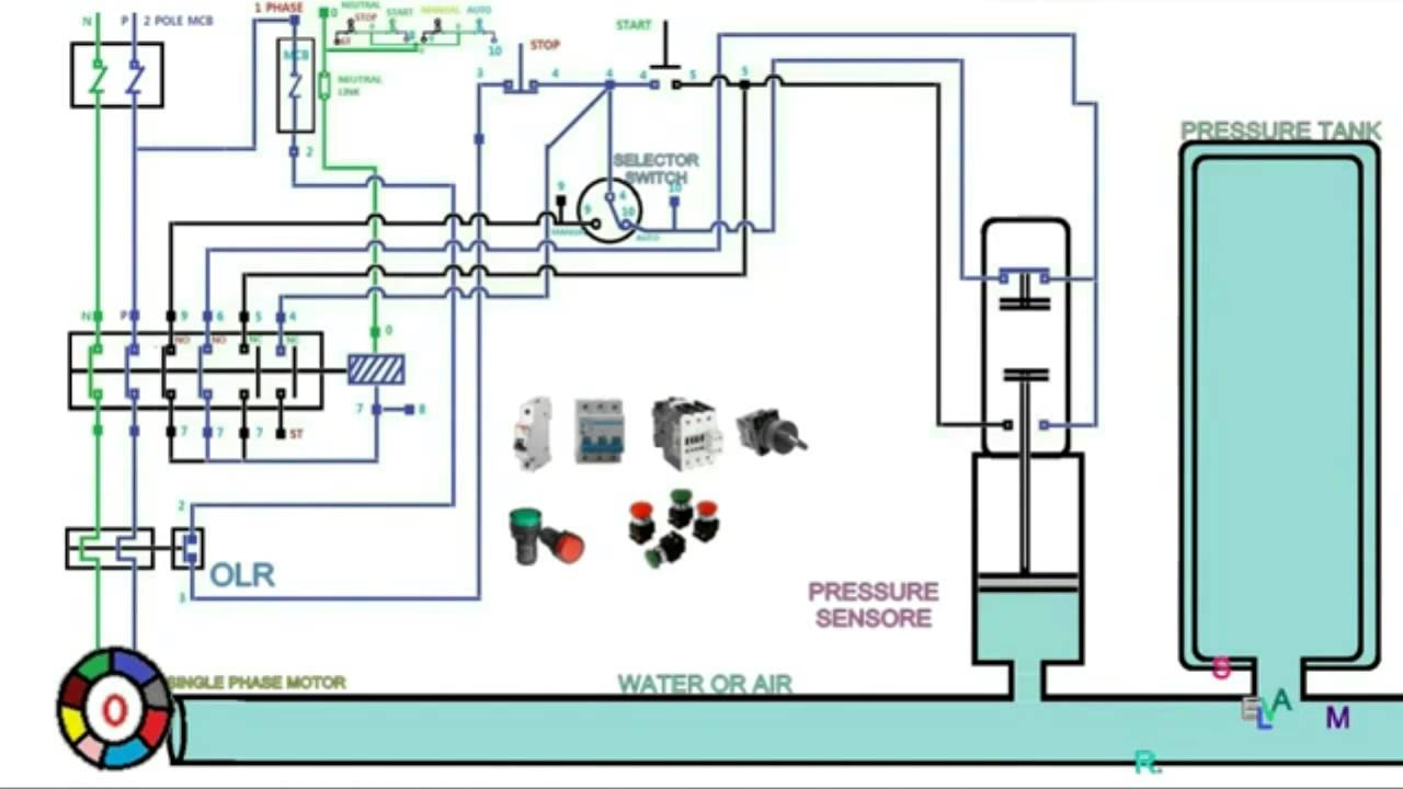
The circuit measures water levels in the tank with the three probes and automatically switches on the pump on the desired low level of water and automatically switch it off on the desired high level of water. The circuit is completely automatic which starts the pump motor when the water level in the over head tank goes below a preset level and switches off the pump when the water level in the over head tank goes above the full level. Controller circuit and indicator circuit. The controller system will automatically switch on the pump motor. Six level wireless water. The circuit can be divided into two parts.
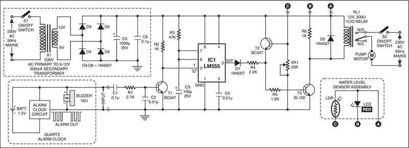
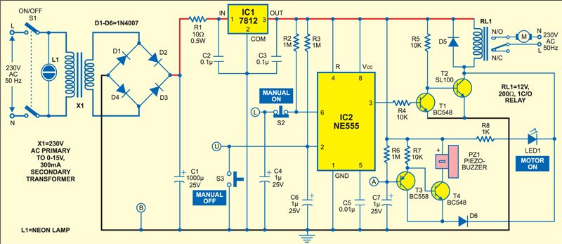
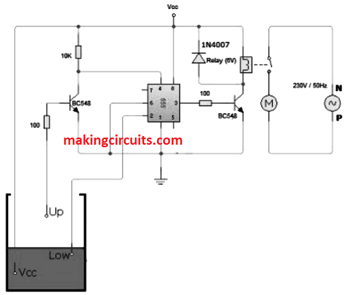
This is an automatic water pump controller circuit diagram using an ne555 timer. The article describes a simple low cost automatic water pump controller circuit. The timer in the circuit is used to time out c3 and time in c2 to understand it just identify the contact of the timer in the circuit u. Simple automatic water pump controller. Automatic pump controller using 555 timer. Add tip ask question comment download.
The circuit can be used for variety of purposes like filling pools tanks container washing machines etc. 1 to avoid the aforesaid problem. Similarly it gets switched off when the tank is filled up. Add tip ask question comment download. Low medium n high. For this purpose i have designed an automatic water pump controller circuit that can monitor water level in your tank and when water reaches maximum threshold of the tank this circuit turns motor off.
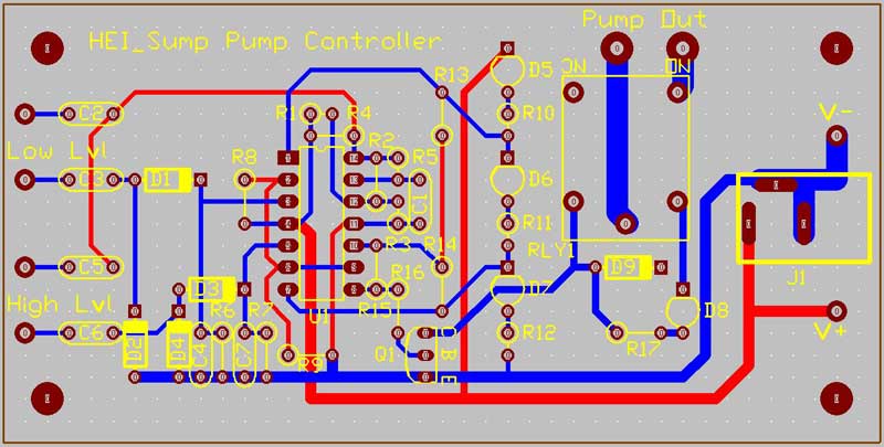
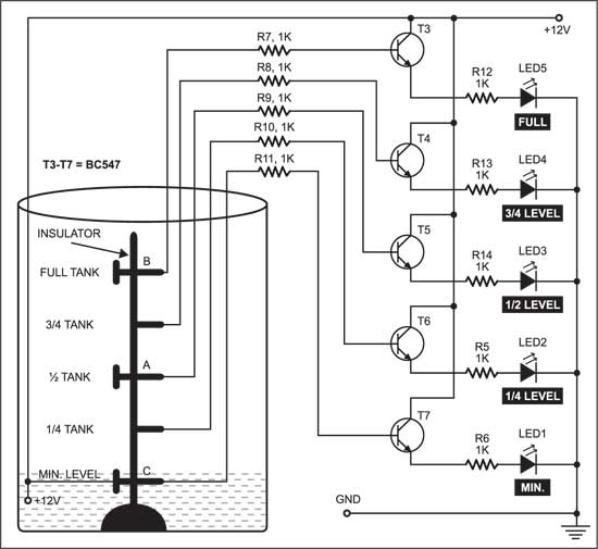
The cycle repeats thereby automating and controlling water flow to the tank. The three probes. Here is the complete guide step by step. The circuit uses 6 transistors 1 ne555 timer ic a relay and few passive components. They often use the pump automatically. Need ckt diagram fr three motor having star delta starter on same mcc such that only 2motor can start simultaneously not 3rd one.
Our project consists of two water level sensors one fixed at the top and other at the bottom. And it can not only use for controlling water level but you can use it for many other liquids. The circuit will automatically switch on any water pump motor when the level of water in a tank reaches below from the required level and automatically switch off the pump after filling the tank. Please describe the the control circuit diagram of automatic star delta starter with timer for 3 phase motor. In the countryside water is very important. Single phase submersible pump control box wiring diagram 3 wire submersible pump wiring diagram in submersible pump control box we use a capacitor a resit able thermal overload and dpst switch double pole single throw.
Here is a very useful project of an automatic water pump controller circuit. A simple but very reliable and effective water level controller circuit diagram is shown here. Keep the clock nearby your sleeping bed and switch on the circuit before going to sleep. Motor power rating star or delta. In the morning as the alarm rings you can switch off the alarm and if you like go to sleep again. Here is a low cost and simple automatic water pump motor controller circuit fig.
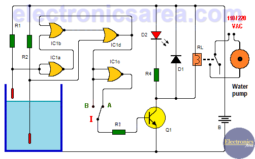
Built around only one nand gate ic the circuit is simple compact and economical. Probe d is positioned at the bottom level of the tank while probes a b and c are. The heart of this pump controller circuit is a ne 555 ic. Similarly when water level goes below say 10 of total tank capacity this circuit turns the motor on enabling water to fill the tank. It works off a 12v dc power supply and consumes very little power. Here we have manipulated the flip flop inside the 555 timer ic.
You just have to set your quartz alarm clock connected to this system at the appropriate time of water supply. The most to use the groundwater to dig as a pond and for the convenience.
Gallery of Automatic Pump Controller Circuit Diagram