Assortment of carling technologies rocker switch wiring diagram. With independent lamp.

Rocker Switch Wiring
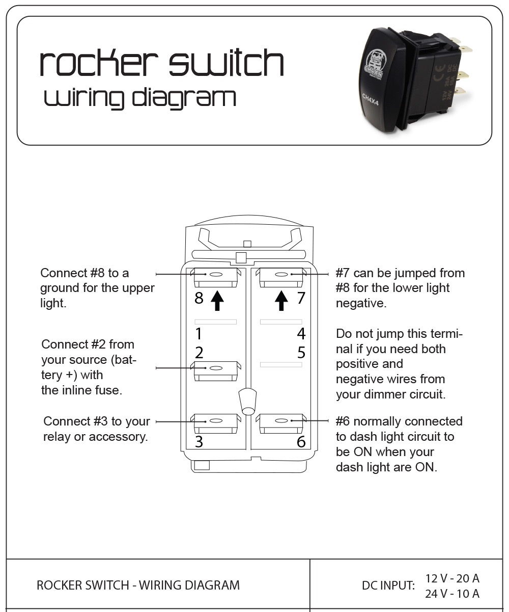
Carling switch wiring diagram 5 pin. Carling switch wiring diagram arb carling switch wiring diagram carling dpdt rocker switch wiring diagram carling hazard switch wiring diagram every electrical arrangement is composed of various distinct components. 5 pin relay wiring diagram 5 pin relay wiring diagram 5 pin relay wiring diagram 87a 5 pin relay wiring diagram driving lights every electric structure is composed of various unique components. To wire a 3 pin switch to a 5 pin rocker switch you need to find out what your 3 wires do. Or these terminals can be ignored for non backlit switch banks. The wiring diagram to the right will show how to wire and power this 12v 20amp on off on 3 way carling contura rocker switch. All carling switches are rated at 20amps.
It reveals the elements of the circuit as streamlined shapes and the power and signal connections between the gadgets. Euro switching push the bottom of switch to turn on. Mud supplied carling switches are 12v only. Aurora wiring harnesses are set up as black groundnegative red positive blue power to lighting product. With nbl bracket only 2. Each component ought to be placed and linked to other parts in specific way.
Otherwise the structure wont work as it ought to be. A wiring diagram is a simplified standard photographic depiction of an electrical circuit. Carling switch instructions and wiring diagram look closely at both sides of the main switch body to find the terminal pin numbers. If you are trying to convert a 3 pin light bar switch to a 5 pin rocker switch then please read below. Quality assurance momentary carling lighted 5 terminals 5 pin rocker 5 pin rocker switch wiring diagram wiring diagram comes with several easy to stick to wiring diagram directions. Bulb positioning actuator positioning.
5 6 e 1 2 4 5 3 6 load e1 e2 1 2 4 5 e load load 1 1 2 4 5 e 3 6 load 2 standard switch wiring diagrams carling technologies inc. Carling switches wiring diagram 4 pin carling switch wiring diagram arb carling switch wiring diagram carling dpdt rocker switch wiring diagram every electric arrangement consists of various diverse pieces. It really is supposed to help all of the common consumer in creating a suitable system. Contact terminal will make contact with switching lever isolated terminal does not make contact with switching lever contact terminal switch lever bulb notes. Describing section 5 of the carling part chart switch sealing independent vs dependent lamps. With just a few small jumpers our switch selection can be used for a multitude of different functions.
Each part should be set and linked to other parts in particular way. Us switching push the top of switch to turn on. When wiring this switch you can choose if youd like to illuminate it because of the independent lamp attached to terminals 8 and 7. These guidelines will likely be easy to understand and apply. If not the arrangement wont function as it should be.
Gallery of Carling Switch Wiring Diagram 5 Pin